James Ots
-
Speed Comparison
10/30/2017 at 23:30 • 0 commentsAfter much reading of CP/M source code and stepping through the code in Joyce for DOS, I finally tracked down the vital byte to change so that drive C: is the default drive on my PCW. Now when the computer boots it looks on drive C: for PROFILE.SUB and doesn't care if there's no disk in drive A:. Although it still switches the drive motor on for some reason.
I thought I'd do a little speed comparison, so here is a programme I wrote a few years ago which loads a photo on the PCW, first being loaded from the floppy disk, and then from the SD card.
-
No Floppy Drive Necessary
10/30/2017 at 00:24 • 0 commentsI've now got my PCW to load the FID file from the SD card, which means there's no need for a floppy drive at all to boot the PCW. Unless you want a PROFILE.SUB file to be loaded, as it still looks on drive A: for that.
I spent quite a lot of time reading the disassembled source code of J15CPM3.EMT until I could work out how FID files are loaded. I then patched it so that it would load the FID file out of the J15CPM3.EMT file itself.
It's slightly convoluted. I added some code onto the end of the EMT file and also modified a couple of existing bits of code. The boot process now goes like this:
- ROM code loads first 48Kb of SD card (which contains J15CPM3.EMT) into pages 0, 1 and 2 or RAM.
- Execution starts at 0000h. The existing code sets the stack pointer, and then I've replaced the next 13 bytes with a call to a880h (where the EMT file would normally end, but where my extra code now sits), followed by some NOPs.
- My code switches page 16 into bank 0 and copies the rest of the extra code from the end of memory to the start of page 16.
- The code then executes the instructions I had to replace in order to call my code, and then returns.
- The rest of the normal boot process continues, until it gets to loading FID files.
- At this point, I've replaced 8 bytes with my own code which switches page 16 into bank 2 and jumps to it.
- This code loads the FID (which was also tacked onto the end of the EMT file) to 0100h and sets up an FCB entry at 005ch.
- It then overwrites the 8 bytes I'd replaced with the original code, and then copies some more code from page 16/bank 2 into bank 1, and jumps to it.
- This code switches bank 16 back out, removes a call to a file closing routine, and then calls the original code which would have been called just after loading a FID file from the disk.
- After this returns, the original call to the file closing routine is reinstated.
- I then call the original FID loading code, so that extra FIDs could be loaded. (Or I would, if it worked. This is commented out right now, and I jump to the end of the FID finding code instead.
- The rest of the boot process continues, the CCP is loaded and it tries to load PROFILE.SUB from drive A: I need to fix this.
Hopefully I can remember how this works tomorrow. If I can't remember what any of this means after a night's sleep then I'll re-write it!
Here's a video of the computer booting. Unfortunately, my phone doesn't like focusing on the screen, so a lot of it is rather blurry.
-
SD Card Drive in CP/M
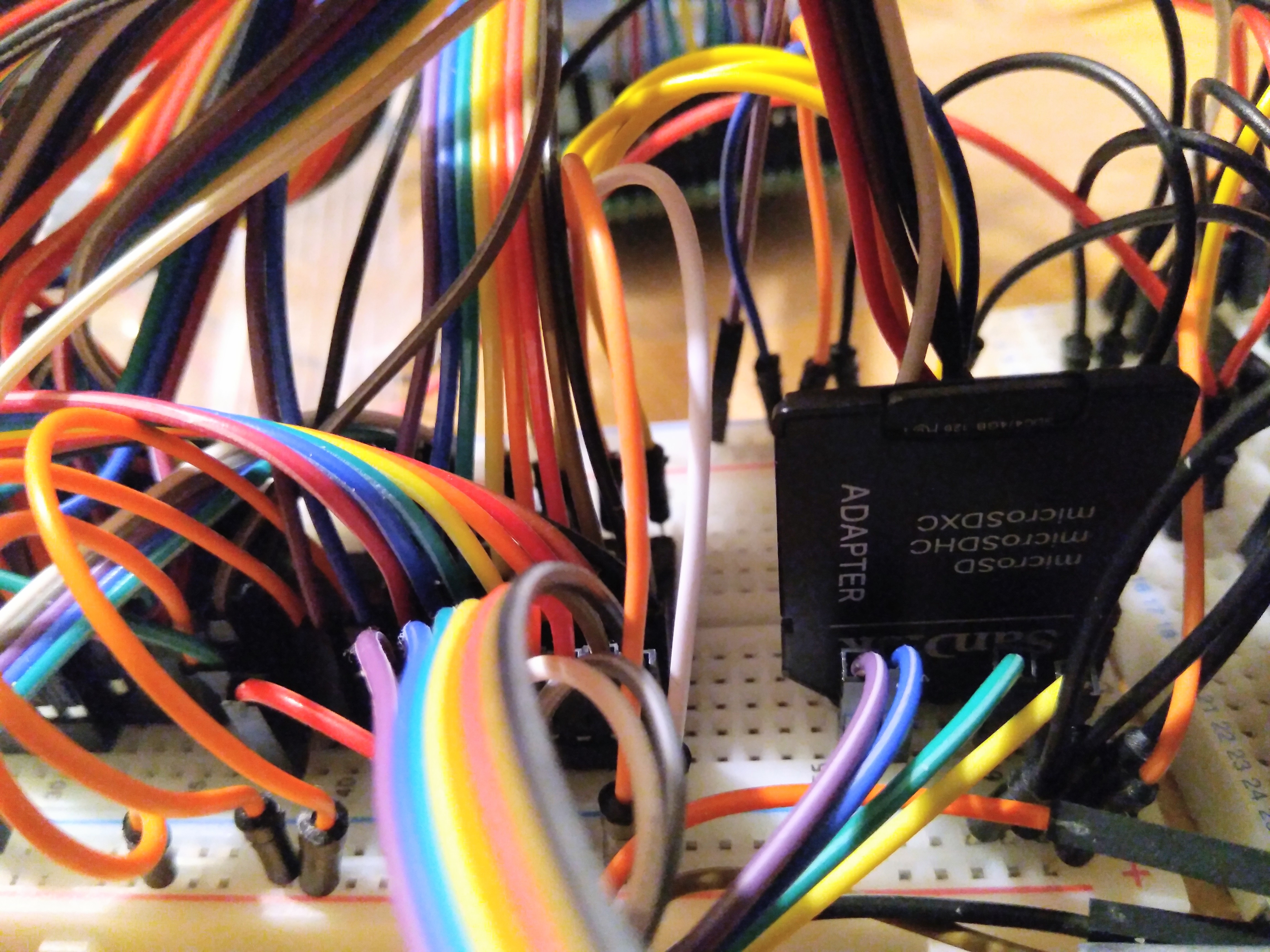
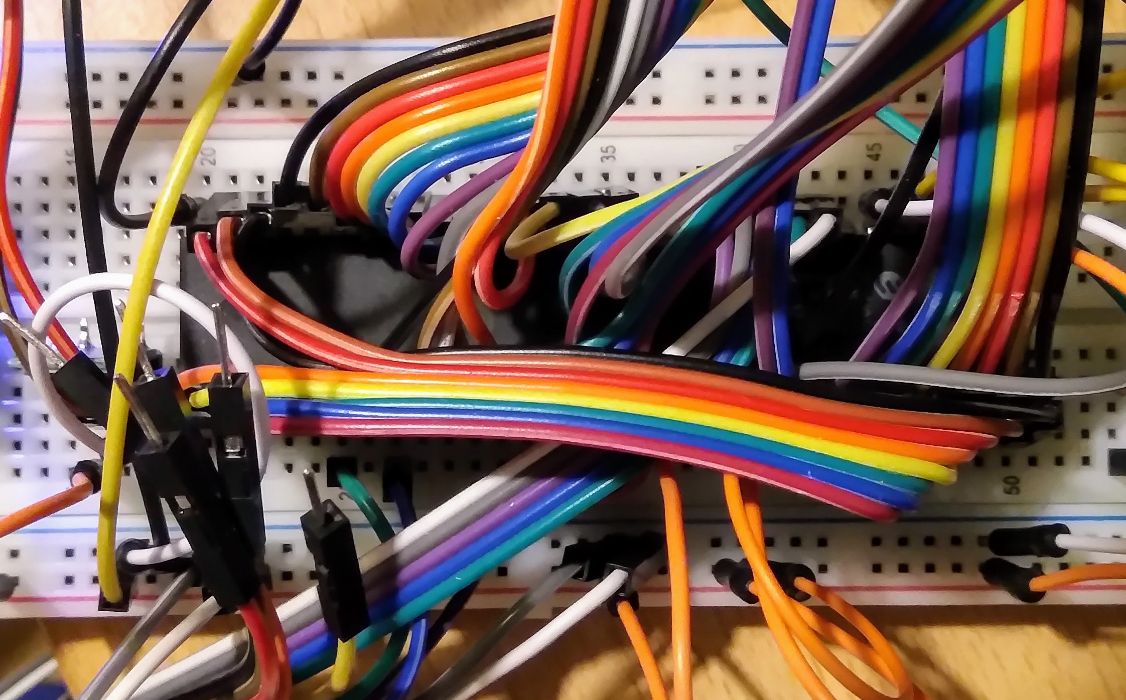
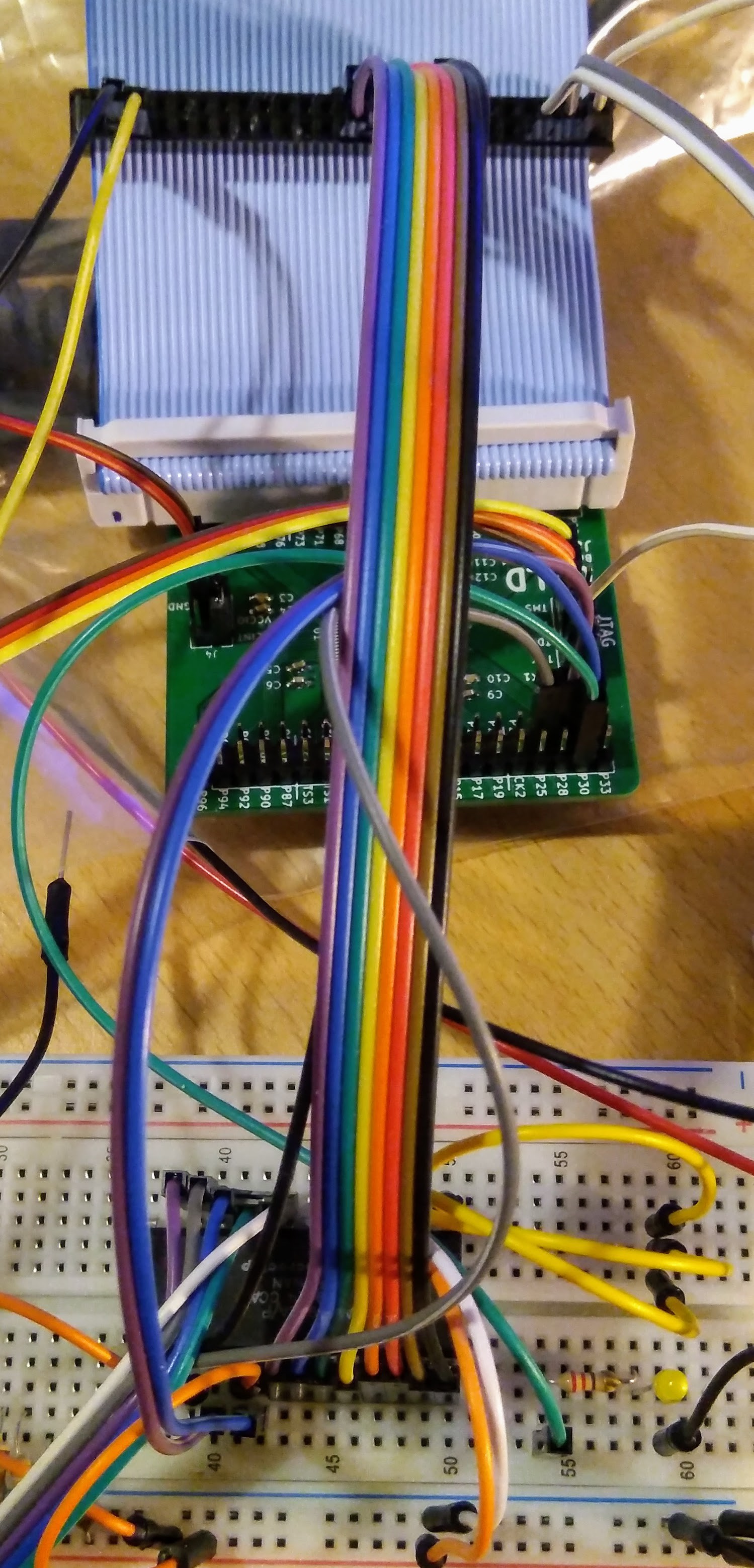
10/27/2017 at 21:38 • 0 commentsSo I got my computer to boot off the SD card, but that was just blindly reading the first 40Kb off the SD card into memory and executing it. Once booted, CP/M knew absolutely nothing about the SD card. So I had to do some more coding. But before I get onto that, here's a colourful picture of the circuitry at the moment:
![]()
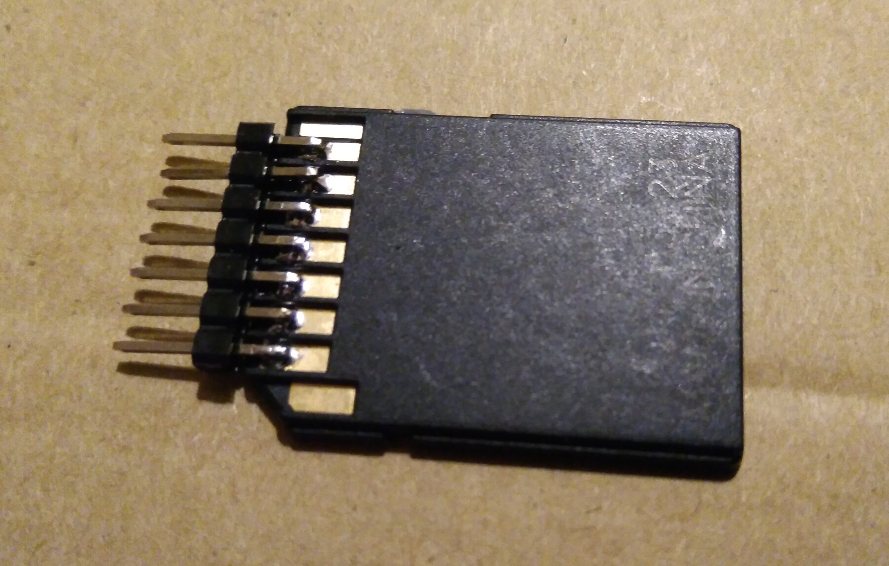
And a picture of my home-bodged SD card adaptor. I'm saving money for a trip to Canada for a family wedding next year, so I'm making any savings I can at the moment. Fortunately the connections on an SD card line up nicely with a 0.1" pin header:
![]()
Now, on to the programming.
I only had version 1.14 of CP/M Plus on my PCW, which doesn't support FID files (loadable device drivers), so I had to get hold of version 1.15 before I could start using the SD card in CP/M. Oddly, when I put J15CPM3.EMT onto the SD card, it started to boot, but then got stuck just before the A> prompt appeared. I spent quite a lot of time trying to work out what was going on, including disassembling J15CPM3.EMT. I'd already done some work on this before, but I got further this time, as I wrote a utility to put all the bits of the file into the right places in memory before disassembling. And then realised I could use the Joyce emulator and do a memory dump. But it all came to naught, as I couldn't work out what was going on.
Eventually I discovered the problem. J14CPM3.EMS fits into 40Kb, but J15CPM3.EMT is slightly bigger. To make things easy (hah!) I changed my ROM boot programme to just read the first 48Kb from the SD card into the first 3 pages of memory. Unfortunately, as I had these pages loaded into banks 1, 2 and 3 instead of 0, 1 and 2 (because my bootstrap programme is in bank 0), and because I had the stack at the top of bank 3, the stack was getting clobbered. I moved the stack into bank 0, and it suddenly started booting with v1.15.
The next thing was to get a FID file working. To make things easy, I first tried developing a simple FID file using Joyce — it gave me the ability to experiment with different compilers and tools without running out of disk space, or waiting for ages for things to compile and then not work. Once I had a simple driver working which just showed a message on boot, I started working on the PCW.
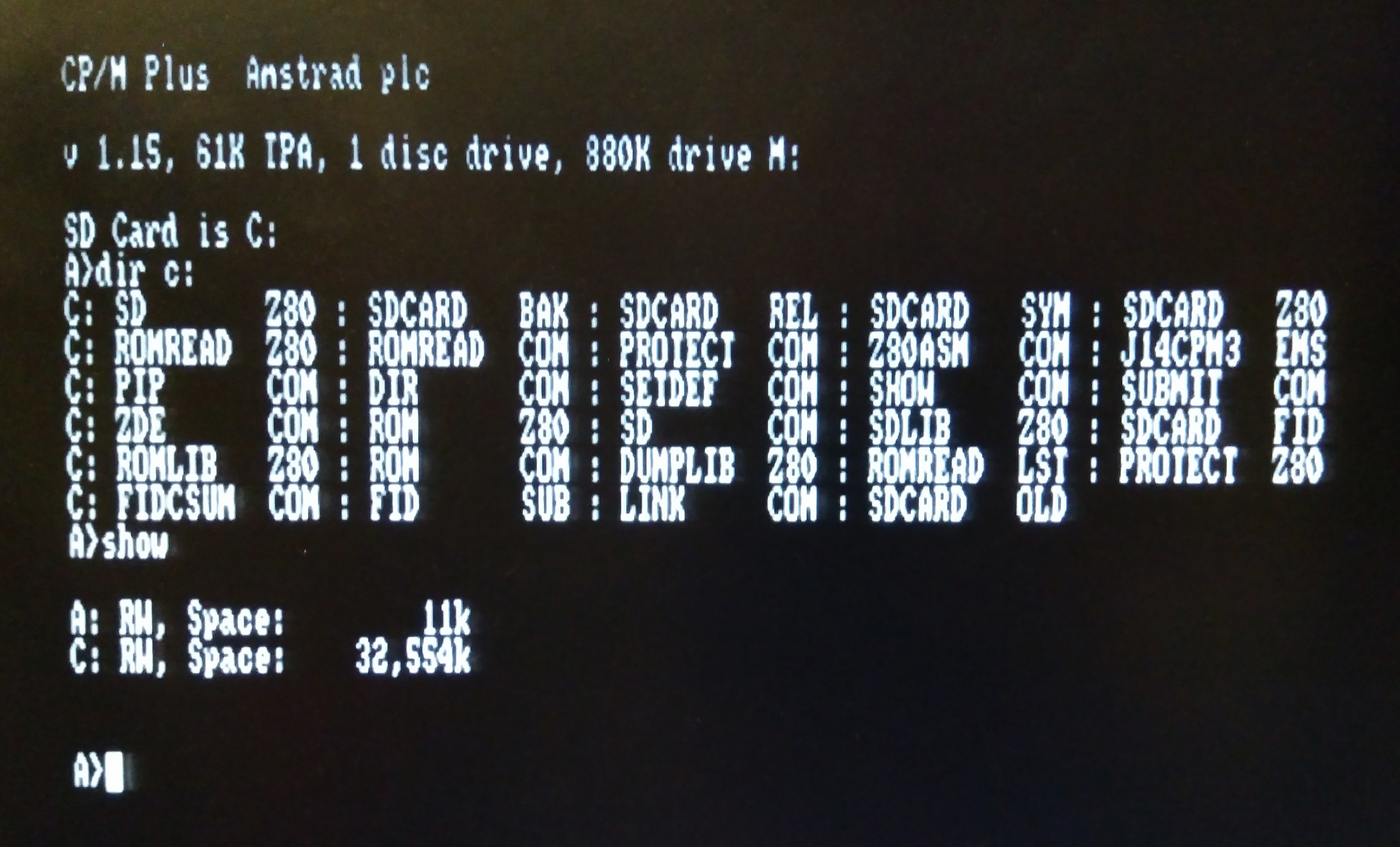
Writing the FID file was actually fairly simple. I've already created routines for reading from and writing to the SD card, so it was just a case of putting all the pieces together. The hardest part was creating a suitable DPB, with all the right numbers in the right places. I had a bit of trouble getting confused between logical records (128 bytes), physical sectors (512 bytes) and logical blocks (2048 bytes), but eventually I got it right, and was able to use the SD card as a 32Mb fixed disc in CP/M. I also managed to get a disk definition set up for cpmtools in Linux, so I can also read from and write to the SD card in Linux.
![]()
I have a few things which still need to be done:
- Add some error checking and recovery
- Make sure it works with SD cards other than the ones I have
- Cope with the SD card being removed (and when I have a real SD card socket with a card detect line, use that)
- Have more than one disk, depending on how big the SD card is
And the biggest one (and probably the most difficult):
- Boot CP/M without any floppy drive. Because at the moment, I still need the floppy drive around to load the FID file from. I'd probably have to actually patch CP/M in order to get this one to work.
-
Boot CP/M from SD Card
10/24/2017 at 17:46 • 0 commentsThis feels like quite a milestone in this project. It's pulled together a whole bunch of things I've done previously into one working piece of almost awesomeness.
My PCW finally boots from an SD card. Actually, first it boots from the printer ROM as usual, but then the CPLD makes the EEPROM jump in, which loads J14CPM3.EMS off the SD card into memory and boots it.
At which point CP/M wants to load PROFILE.SUB from drive A:, and as CP/M knows nothing about my SD Card, despite being loaded from it, you still need a disk in the drive. It takes about 3.5 seconds to boot to this point, compared to about 10 seconds when booting from a disk.
If you watch the video, you'll also notice that the screen is filled with rubbish while it's booting. This is because I haven't bothered to initialise it — I should probably initialise it and put a pretty picture or something there while it boots.
A few of the problems I had while getting this to work:
- I hadn't set up the stack pointer before calling a routine, which caused all sorts of random havoc.
- I was running code from the ROM, forgetting that it would be trying to write to unwriteable memory. One of the first things the bootstrap programme now does is copies itself into RAM.
- I forgot to use the WAIT signal when the SPI code is running in slow mode during SD card initialization, which meant my code was trying to send things before the previous data was sent.
- I hadn't anticipated how fast the SPI interface would be when running in fast mode using the PCW's 32MHz clock — it is so fast that it finishes sending a byte to the SD card before the OUT instruction has finished executing. Because the IORQ and WR lines were still low, it then sent the same byte a second time. I added a flag into the VHDL code so that it won't send another byte until another M1 signal has been seen.
- After writing the bootstrap programme to the ROM I hadn't bothered to protect it, so when I made mistakes and the code ran amok, it ended up clobbering the bootstrap programme. I wrote some utilities — UNPROTECT and ROMDUMP to help.
- I made all sorts of other silly Z80 assembly mistakes, such as somehow forgetting to actually call my sd_read_block routine when trying to load CP/M!
However, it is working now, and I have created a few Z80 libraries (SD, ROM and DUMP) to make it easier to do this stuff.
I now need to patch CP/M to recognise the SD Card as an actual disk drive (or several disk drives). If I was going to keep drive A: around I might have just used FID files, but if there is no drive A: (or if I want to be able to boot quickly without looking at drive A:) then I'm going to have to patch CP/M instead, which should be another interesting challenge.
-
Boot from ROM
10/21/2017 at 11:51 • 1 commentI can now boot my PCW from ROM, instead of using a disk. Unfortunately, it doesn't boot into CP/M or LocoScript — it just boots into my test programme which turns the screen and buzzer on and wait for you to press space bar, after which it inverts the screen and turns the buzzer off. Not at all useful, but an easy programme to write to prove it's really booting from my ROM.
How does it do it?
When the PCW is switched on, first it loads a small programme from the ROM in the printer controller into RAM. Once this is done, it sends 0 to port F8, which tells the PCW to stop reading from the printer ROM, and to use normal memory.
My CPLD watches for this command, and when it is seen it goes into its own special boot mode, where the first page of ROM is in all banks, and execution then continues at address 0002. At this point my code sets up the banks of memory it really wants and then writes to port B0 to turn ROM override mode off.
You can also disable ROM override mode by setting one of the CPLD pins high, so it's still possible to boot the computer normally.
And here's a short and very boring video of my PCW booting from the ROM:
-
ROM
10/21/2017 at 07:34 • 0 commentsAfter getting the extra RAM to work, I added an EEPROM as well. After which my PCW started randomly crashing. It's taken several days to get to a state where it works reliably, and I think I'm there now. There were several mistakes I'd made. For a long time I thought it was the breadboard's fault, as when I built my homebuilt Z80 computer then I had a bunch of dodgy breadboards which didn't make good electrical connections. I'm not totally sure this one is fine, but I don't think it's the main problem. I wondered whether I was drawing too much power, although this seemed unlikely. I hoped I hadn't blown up my PCW, but disconnecting my external circuit proved that I hadn't. After fixing a few silly mistakes in the VHDL code and still not curing the crashes, I tried leaving MDIS floating when I wasn't disabling the internal memory, instead of driving it high, and that seems to have worked.
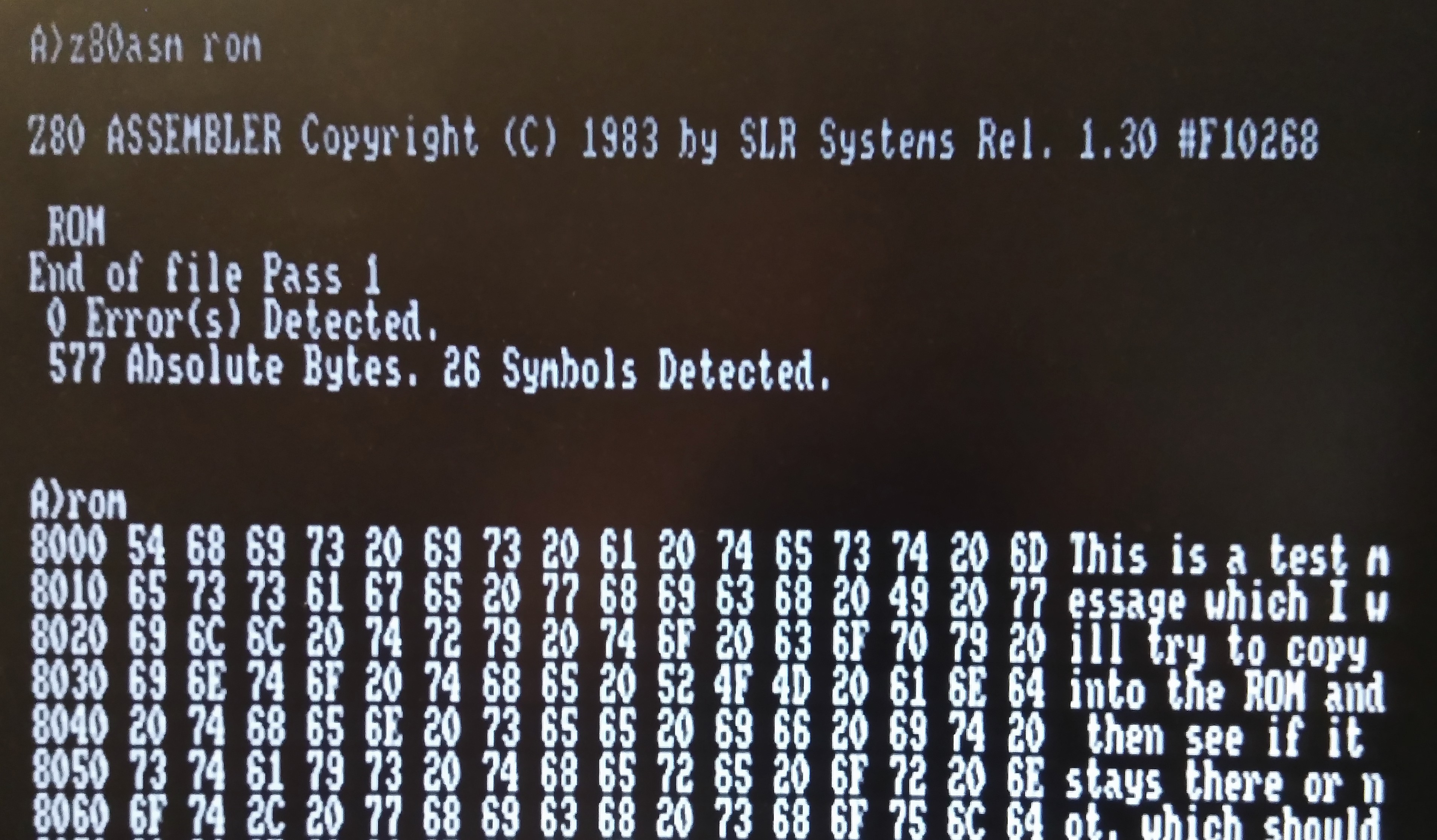
Anyway, I've managed to copy some data to the ROM and have it still be there when I switched the computer off and on again:
![]()
Now, unless it starts randomly crashing again, I can get onto the fun stuff, which is making the PCW boot from the ROM, and then adding an SD card.
-
Big M:
10/16/2017 at 21:09 • 1 commentI bought an LCD screen on eBay about three weeks ago. It said it was UK stock, being shipped from Leicestershire — just down the road from Coventry, so it should have arrived really quickly. Unfortunately, it was actually shipped from Hong Kong, so it only just turned up today. So I had something fun to play with this evening:

However, that's for my homebuilt Z80 project (it's going to connect to a Raspberry PI Zero to make a serial terminal), so I've had to put it to the side for now. Instead, I fixed my PCW's memory expansion.
It took a while. I improved my Z80 test programme, to copy things around a bit more and give me a good idea of what works and what doesn't. As I'd been informed, when I write to a high RAM page it does actually write to a low one instead — it has absolutely no idea that my memory is there. To start with, there was some corruption in the text I was copying though. After connecting up my logic analyser I realised that I'd managed to get the OE and WE pins the wrong way round. I swapped them, and hey presto — still no extra memory. :(
As far as I could tell, the PCW had no interest at all in my memory, connected to the external connector. And then I suddenly remembered that the PCW's memory is connected to a separate set of connections on the gate array, and that there's a mysterious signal on the edge connector called MDIS. Perhaps this disables the internal memory and lets the external memory be used? I connected the RAM_CE signal to MDIS and hey presto — the memory was finally recognised, and my test programme worked.

Now I'm feeling quite pleased with myself! Although my breadboard is looking a bit of a mess:
![]()
-
Memory and Disassembly
10/16/2017 at 08:23 • 1 commentI tried to add an extra 512Kb of RAM to my PCW at the weekend. I used an as6c4008 static RAM chip to make things easy — no need to mess around with refresh signals or RAS and CAS and address decoding — and borrowed some VHDL code from my homebuilt Z80 project so that it would be switched in when a bank select command was sent requesting banks 32-63. I was hoping that this would be enough to make it work, but it doesn't seem to be.
The documentation I'd seen said that the PCW will use the existing RAM if external RAM doesn't exist, but there's no mention of how to detect the external RAM. I wrote a small machine code programme which switches banks and copies data around, and the data I copy gets corrupted, which seems to indicate that the computer is writing and reading from my external RAM and the internal RAM at the same time.
I started disassembling CP/M (the J14CPM3.EMS file) to see if it could throw any light on the matter, and I think I've found the RAM detection code. Memory location 007F contains the number of 16Kb pages of memory in the system, so I just had to find where this location was written. I found one location, and it is preceded by a loop of bank switches and memory reads and writes, so it looks like it's the right bit of code. I haven't properly worked out the algorithm yet. However, I'd be surprised if there's any code which can tell the gate array not to access internal memory.
(There's also still quite a large chance that my VHDL code isn't quite right.)
As an interesting aside, I was intrigued by how J14CPM3.EMS copies itself into memory. The file is loaded into memory at 0000 and execution starts there too. It then switches banks and copies parts of itself into other locations in memory using LDIR. It also zeroes out some parts of memory using LDIR too. All pretty straightforward so far.
But then it comes to the weird part. There's a routine which copies 128 byte blocks of memory in reverse. It copies 128 bytes from SOURCE to DESTINATION, then it copies 128 bytes from SOURCE-128 to DESTINATION+128, then from SOURCE-256 to DESTINATION+256. At the moment I'm at a loss as to why it would do this. Actually, I'm still not quite sure I haven't misunderstood the code, because it seems such an odd thing to do.
-
Sound!
10/13/2017 at 21:32 • 0 comments![]()
I got an IDC connector today, which meant I was able to connect the PCW data bus to my AY-3-8912A sound chip without having to go through the CPLD. While I was about it I also moved the clock signal onto one of the CPLD's clock pins and took the video signal directly to the video output circuit too.I had to fiddle with my logic analyser a little — I was expecting to be able to map ports 0xA8 to 0xAB to the sound chip, and have address line A1 connected to BDIR and A0 connected to BC1, but it wasn't quite that simple — I had to invert A0 when A1 is 1.
Then all of a sudden, Head over Heels started detecting the joystick and sound card, and I started to get the most musical sounds I've ever heard from a PCW.
I haven't sorted out the sound output circuit properly yet, so for this video I just connected all the three channel outputs together and fed them through my guitar amp — hence the distorted sound! It was also quite hard holding the wires together at the same time as holding my camera and operating the joystick. So, not the best video you'll have ever seen:
-
Kermit
10/12/2017 at 23:33 • 0 commentsHaving said that all I did this evening was cleaning, I then remembered I had some files I wanted to transfer to the PCW. So I plugged in my homemade serial port and got copying.
When I got my first PCW, the LocoScript disk was corrupt, which meant I didn't have MAIL232.COM available for copying programmes from my PC to the PCW. So initially, the only way of copying files across was by using PIP. I can't remember the exact details of how I did it, but I believe it involved sending MAIL232 in hex format over a slow connection, which I then had to compare visually and correct and transmission errors. Then I think I had to write a programme which converted the hex file to an executable — I don't remember if this was in assembler, or Mallard BASIC. Once MAIL232 was working, I was then able to transfer kermit, which is the software I now use.
After doing a fair amount of experimenting I managed to get a good set of settings for making reliable transfers, although I can't go very fast before things start to break down. These are my settings (I'm using ckermit on Ubuntu on the PC):
Type this on the PCW:
A> setsio 9600 int on hand on xon off
A> kermit
kermit> set baud 9600
kermit> set flow-control off
kermit> set file-mode binary
Type this on the PC (I know, sudo is bad. But I keep forgetting to set up permissions for /dev/ttyUSB0 properly):
$ sudo kermit
kermit> set line /dev/ttyUSB0
kermit> set baud 9600
kermit> set carrier-watch off
kermit> set flow-control rts/cts
kermit> set file type binary
To send a file, first I type 'get filename' on the PCW, and then 'send filename' on the PC. To receive a file I have to type 'receive filename' (not get) on the PC and 'send filename' on the PCW.