 James Ots
-
Cleaning
10/12/2017 at 22:25 • 0 commentsThis evening I was cleaning. I cleaned my spare 3" disk drive. Using isopropyl alcohol and cotton buds I scrubbed away all the old drive belt rubber from the pulleys, and then I fitted the replacement drive belt. I haven't tested it out yet. I should have taken photos, but as I've done this before it didn't seem like something which needed documenting.
After that, I took my PC apart and took all the RAM sticks out and re-seated them, and then disconnected and reconnected all the drives and power, and then squirted compressed air all over the place. Now I'm coughing from all the dust, but hopefully my PC will now stop segfaulting all the time, and I'll stop wanting to throw it out of the window.
Everything else I wanted to do was dependent on getting some more bits and pieces first.
-
Memory Musings
10/11/2017 at 13:24 • 1 commentThe Amstrad PCW comes with either 256 or 512 Kb of memory installed. And it's easy to upgrade — you just have to add extra RAM chips and flip some DIP switches (unless you have a really early machine, where you have to do some soldering).
But you were also able to buy an external RAM pack (or 'RamPac' as it was branded), which you could just plug in and go. How did the PCW know that there was extra RAM available? I haven't been able to work this out. Does it perhaps try writing to different RAM banks and seeing if it can read the same values back, at startup? I will have to test this theory.
I looked at the motherboard schematic for clues, and found it difficult to even find the DIP switches. Eventually I found them, and they're in quite a surprising place — they are connected to the CS and A0 lines between the printer controller chip and the gate array. The DIP switches change whether the lines are pulled high or low. I guess that when the PCW is operating normally then it drives these lines, and the pull-up/down resistors are ignored, and when it wants to know the switch values it floats the lines and reads their values. It's an interesting way of using a pin for two different things.
-
Joystick
10/10/2017 at 20:51 • 0 commentsToday I was looking up how the PCW's memory management works, when I came across information about PCW joystick ports in John Elliott's very useful PCW Hardware document. And I remembered that I have a joystick which someone gave me, which I've never used. It seemed like it would be the perfect thing to add to my PCW to test out some really basic CPLD code.
A PCW joystick is very simple — it's pretty much just a bunch of microswitches which connect one of the output pins to ground when the joystick moves in the appropriate direction, or the fire button is pressed. So you just need to add pull-up resistors to each of the outputs and feed them into the CPLD. In the CPLD this code is sufficient to implement a Kempston joystick interface:
if clk4'event and clk4 = '1' then
   if iorq_n = '0' and rd_n = '0' and a(7 downto 0) = "10011111" then
      d(7 downto 0) <= "000" & (not joy_fire) & (not joy_down)
         & (not joy_up) & (not joy_left) & (not joy_right);
   else
      d(7 downto 0) <= "ZZZZZZZZ";
   end if;
end if;
And it works. I just played Head over Heels with a joystick for the first time. To be honest, I think I prefer using the keyboard though!
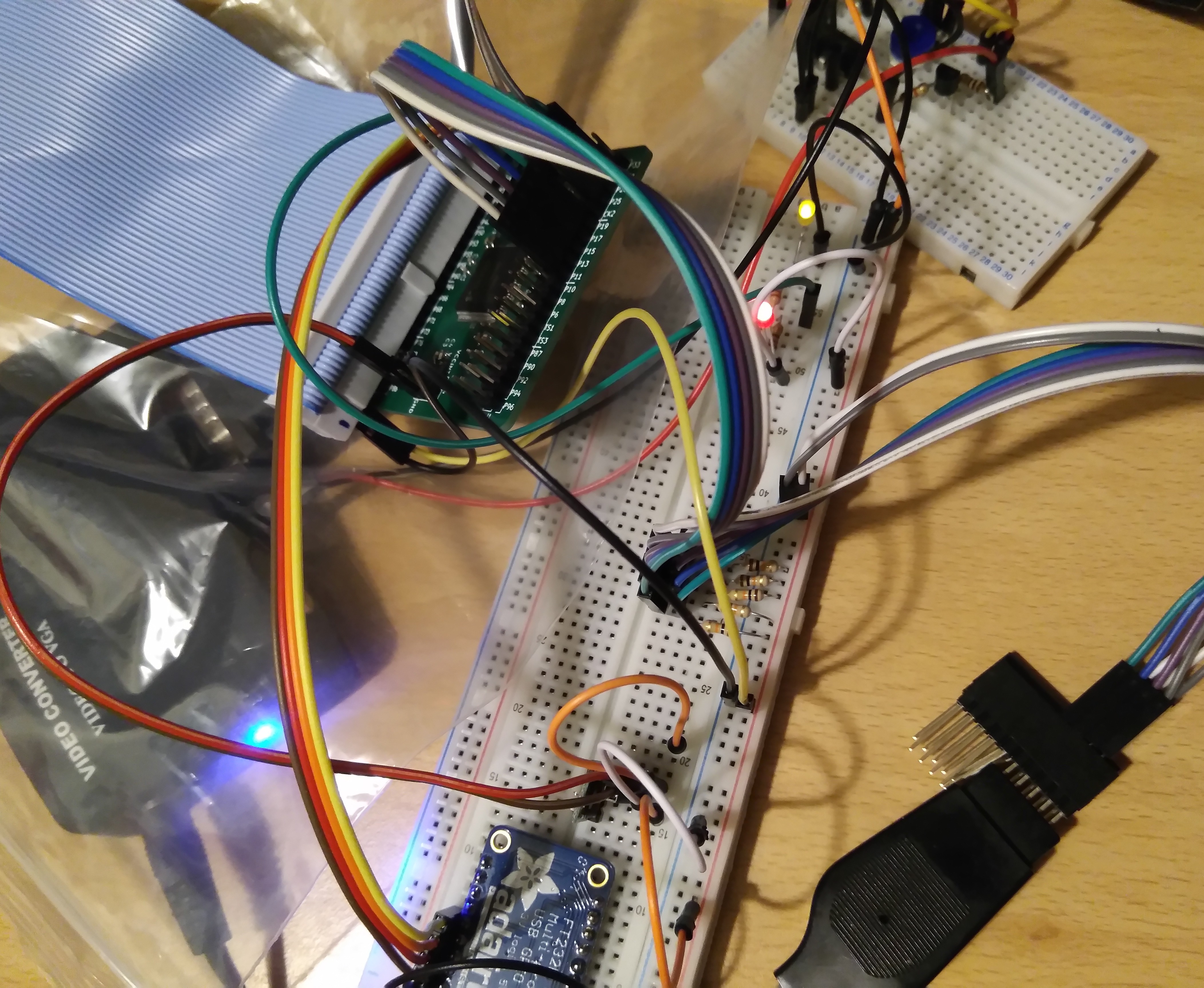
![]()
As you can see, the setup I have so far isn't pretty. The CPLD board is sitting on a plastic bag to make sure I don't short it out on anything. The video circuit is at the top right, with the red and black wires jammed into the S-Video socket on the Video Converter. I also had to improvise a socket for the joystick connector. But hey, it all works for now, and I can make a PCB later (or put it on stripboard).
-
Fixed CPLD
10/09/2017 at 20:50 • 0 commentsToday I went back to trying to get my CPLD to work. I suspected that there's probably a problem with my soldering, so I wrote a configuration which set alternate pins to 1 and 0, so that I'd be able to test for shorts. I loaded it and tested all the pins (by connecting them to an LED), and they were okay. So I switched the 1s and 0s and tested again, and this time I found a pin which should have been 1, but was set to zero. It was next to one of the ground pins, and although the pins looked ok through a magnifying glass I plugged in my soldering iron anyway, and ran it between the offending pins. Then I tested it again, and the pin was working properly. I plugged the PCW in, and it also worked properly. Hooray!
I haven't done anything useful with the CPLD yet — so far I just have an LED connected up to A7 which flickers, and I've routed the VIDEO and NSYNC signals through so I can still use them for the external screen.
Speaking of the screen, here's a random picture of Head over Heels on it, after going through the CPLD.

-
External Monitor Working
10/08/2017 at 20:07 • 1 comment
We have a picture on the external monitor! I simplified the circuit I had before - I removed all the op amps and shoved a transistor in instead. Then I spotted another circuit online and borrowed a couple of resistors from it. And I ended up with something just as bad as before. Then I noticed that the colours were inverted, so I fed my signal through the 74HC04 a second time, and I suddenly had a nice stable picture.

I also messed around with the CPLD some more, but it still kills everything when it's plugged in.
-
JTAG Detected
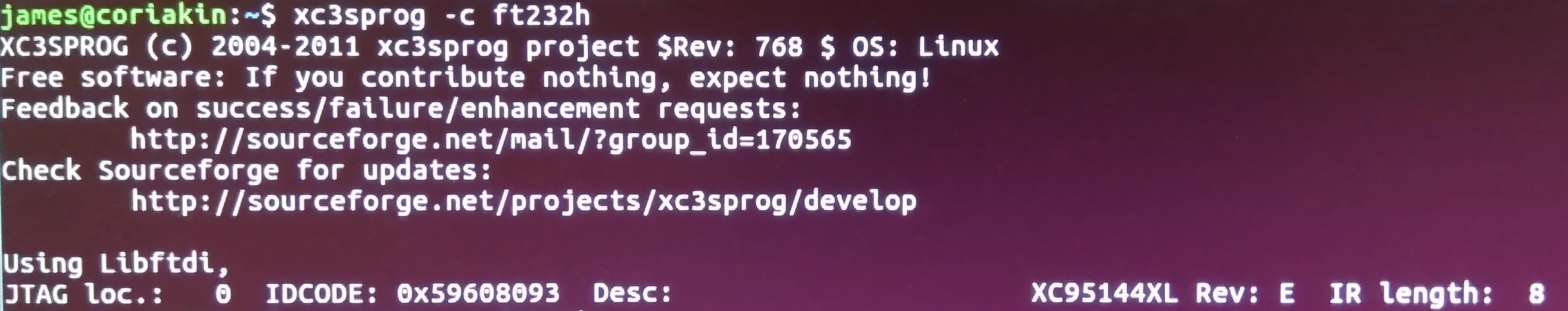
10/07/2017 at 21:50 • 0 commentsI haven't done much on the project today, except to connect up the CPLD to the FT232 and succesfully load my VHDL 'programme' on to the CPLD.

This is always a nice message to see — it shows that I managed to solder the CPLD board at least partially correctly:
![]()
What wasn't so nice was the buzzing noise I got when I switched the PCW on. I can't think where I've gone wrong at the moment. All the pins connected to the PCW should be in a high-impedance state and shouldn't affect the PCW at all. I'm obviously wrong about this though!
-
Another CPLD Board
10/05/2017 at 20:31 • 0 commentsEarlier today I realised that my CPLD boards have enough pins to be able to connect to the PCW. I hadn't really thought about it before, but in the back of my mind I knew that the PCW had a 50 way connector, but my CPLD only has 40 pins on each side. Then I realised that there are a bunch of power pins at the top and bottom of the edge connector, and when I checked, it turns out there are exactly 40 data pins. (Actually, 39, as one isn't connected). As I have a ribbon cable which goes from a 50 way edge connector to a 50 pin socket, I should be able to just connect the CPLD board to the right part of the connector and Bob's your uncle.
The only problem is that the PCW's clock signals don't come out where the GCK pins are on the CPLD, but hopefully 4MHz is slow enough that it doesn't matter. (Even 32MHz might be manageable).
But what is my CPLD board? It's a breakout board I designed earlier in the year for my homebuilt Z80 project, which has a Xilinx XC95144XL on it, two banks of 40 pins headers and a JTAG interface. I use a separate FT232 interface to programme them.
I've made two so far. One is on my Z80 project, and the other got blown up when I got some voltages wrong! I had another CPLD chip waiting though, and the PCBs were made at Seeed Studio, where you get 10 boards at a time, so this evening I put it together.

I'm very short-sighted and usually wear contacts. This is usually just a minor annoyance, but when it comes to soldering surface mount components, it turns into a superpower. If I take my contacts out I can only focus on things which are about 10cm away, or nearer. Which is perfect for fiddly jobs like this. Of course, I wear safety goggles while soldering — you don't want hot flux spitting into your eyes.

Even with super eyesight, it's still pretty fiddly. The first side of the CPLD (the top in this picture) actually ended up being neatest — one stroke of the soldering iron and it was perfectly soldered. The other sides were a bit messy and needed some desolder braid to clean them up. But I think the SMD capacitors are harder to handle — it's just so easy to breathe too hard and send them flying off the desk, or they get stuck to the tweezers with flux, or soldered onto the tweezers by mistake.
I've done a quick continuity test and it looks like it's soldered correctly. Hopefully I haven't overheated the chip or anything, but we won't know until I test it out in a circuit, and that's not going to be tonight.
-
External Monitor
10/04/2017 at 22:33 • 0 commentsI found a circuit diagram online for connecting a PCW to an external monitor. So I made it, connected it to a Video to VGA convert box, and then to an LCD monitor. It does display something vaguely recognisable, but it isn't very good. Whether it's because I built it badly, so it's picking up lots of interference, or because the converter box isn't very good, or because the circuit is wrong, or because the monitor doesn't like the resolution, I don't know. I'm sure I can get there eventually. (I'm kind of tempted to use my FPGA board to convert the signal to HDMI…)


-
Video Analysis
10/02/2017 at 19:04 • 1 commentAs I know very little about video signals, to me the video output of the PCW was some complicated mystery. I knew the sync signal would indicate, somehow the end of the line and the end of the screen, and the other signal would have the picture data, but I wasn't sure what format it was in, and thought it would be too fast for my logic analyser to capture it.
Then yesterday I thought about it and realised that the signal should actually be slow enough, as my logic analyser can capture up to 24MHz signals in theory. So I connected it up, using the serial port I made a while ago — I had put pin headers on the back of the board, 'just in case', and they finally came in useful.

I switched on the PCW and captured 10 million samples of data, and discovered I actually had meaningful data. NSYNC is usually high, and it goes low for 4µs at the end of every line, which is 64µs long (including the low pulse). The VIDEO signal simply toggles between low and high, for dark and bright pixels. Each pixel is 0.0625µs long, making an 8-pixel character 0.5µs long, and a whole line 45µs. (Although there is of course some extra time/space at the start and end of each line).
This is a capture of the start of the first line on the screen:

(The 32MHz clock showed up as 8MHz, since it's faster than the sample rate). You can tell it's the first line of the screen, because if you examine it, it matches the pixels that were displayed:

I put the captures of the first 8 lines together, and got this:
![]()
Which shows that there was some aliasing, as the 25MHz of the logic analyser is a bit too close to the actual signal frequency.
This is a capture showing the end of the screen (where it says Drive is A:). At the end of every screen there's a series of four vertical sync pulses, each of which is 60µs low and 4µs high (the opposite of the signal for every other line).

There are 16 blank scanlines at the end of the screen and 44 at the start. The displayable area of the screen is 32 × 8 lines (256), which makes 316 altogether, plus the 4 vertical sync pulses, which makes a total of 320 × 64µs, which is 20480µs. Multiplied by 50Hz gives 1.024 seconds per screen. Which probably means the timings I have are all a tiny fraction of a microsecond faster than the logic analyser says they are, or that the screen isn't quite running at 50Hz. It's good enough for me at the moment, but I'll probably go and read up about video signal timing now.
-
A Second PCW
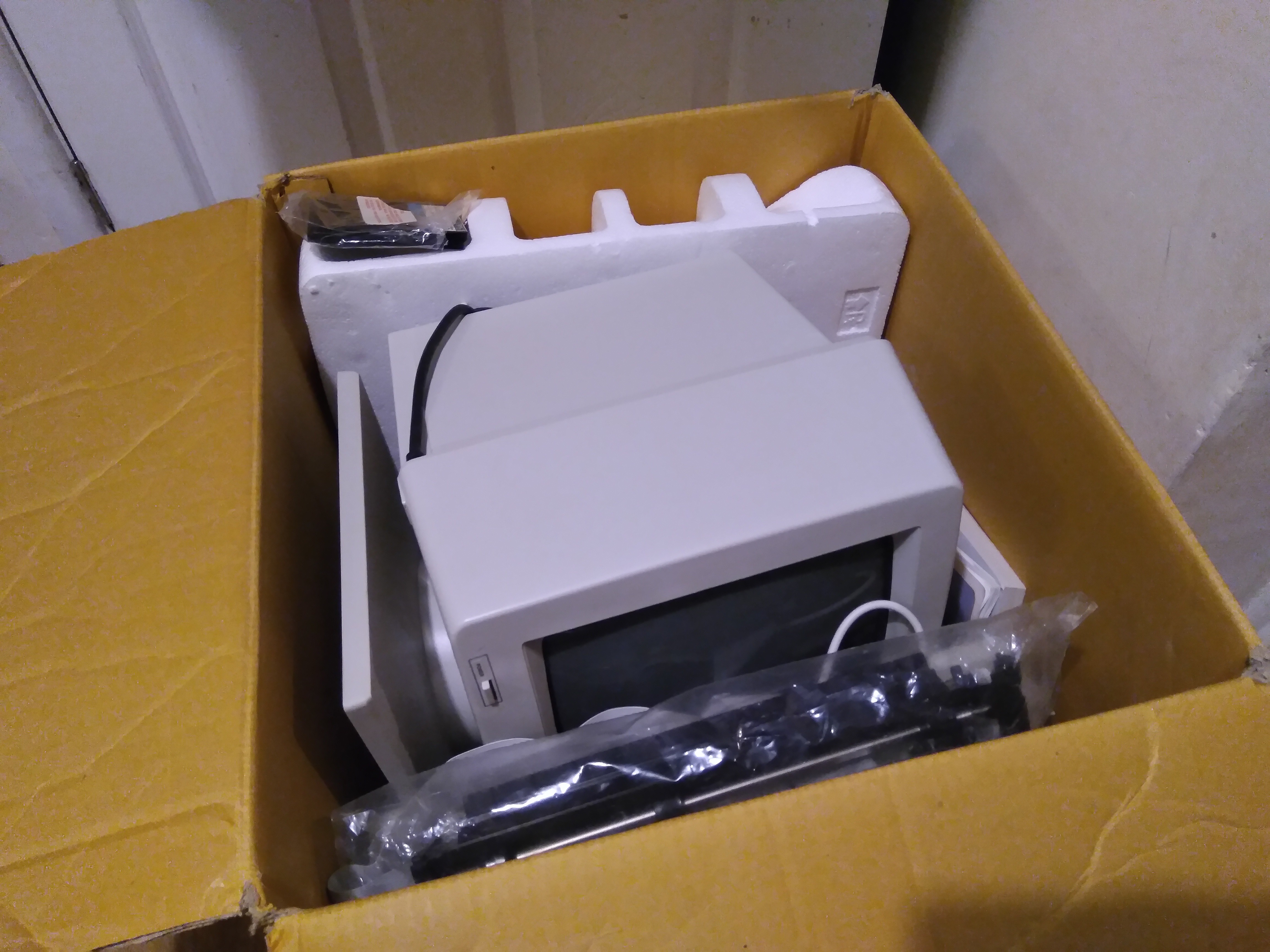
10/01/2017 at 22:13 • 1 commentIf I want to modify a PCW to work with an LCD screen, I thought I should get myself a second PCW, so that I don't destroy the only one I have. So I bought one on eBay for £5.50, and I fetched it from Sheffield yesterday.
![]()
It turned out to be really nice and clean, so I'm going to use that one as my working PCW, and cannibalise the original one for the project. I'd upgraded the old one to 512Kb, so I moved the extra RAM to the new one, and moved the disk drive over as the newer drive needs a new drive belt.
The old PCW's drive belt was pretty much just a rubbery mush when I got it, and was a right pain to scrape out of the drive, but the new one's belt was just a bit stretched, so it should work fine with a replacement.
Although the new computer is much cleaner, there are a few things I don't like about it so much. On the old computer, the Amstrad logos on the keyboard and screen were textured metallic labels, while the new ones are cheap printed plastic labels:


Oddly, while they increased the space on the display so that the label could include the model number, they didn't shrink the space on the keyboard, which makes the label look really out of place.
Also, on the new computer the power and brightness controls were labelled with sticky labels, instead of being printed on the case. I particularly dislikes that the labels were in different fonts, weights and sizes and that POWER was all in capitals and Brightness wasn't, so I removed the labels to see what was beneath them, and discovered what I think is Spanish labelling. Brillo is Spanish for Brightness at least — I guess A. Red means something to do with power.


It's a bit strange that the case would be printed in Spanish and then modified to be in English — especially as the panel below the disk drive is all in English. I wonder if Amstrad made too many Spanish computers and had to modify them to sell in England instead.
Despite these things, the new computer was much cleaner inside, especially the CRT and its electronics, so there's a good chance it'll last longer, so it's the one I'm going to keep.
, display board")
I got the new computer (with the old memory and disk drive) booted up into LocoScript and had a play round, and discovered that the printer works. Which was a surprise, as I'd expected the ribbon to have completely dried out by now. I'd forgotten just how slow the PCW printer was, and my six year-old son was finding it quite interesting. He liked LocoScript's direct printing mode, where it acts a bit like an electric typewriter and prints each line when you press return.

Next up I have a few things I might do:
- Fix the drive belt in the new disk drive.
- Try to get a 3.5" disk drive to work.
- Try to get the PCW to output to an LCD display.
- Connect up a logic analyser and see how everything really works.


, display board")
