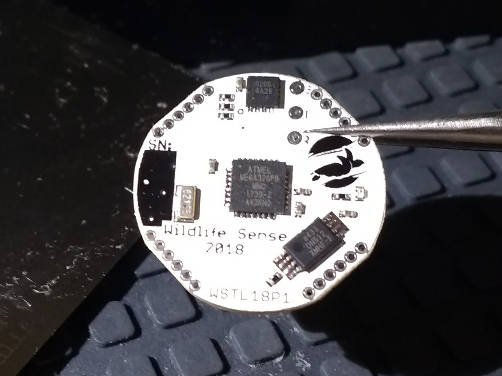
I recently received the stencil for WSTL18 from OSHStencils. With only a handful of components I already had waiting on my workbench, I was able to quickly assemble three prototypes.

The four main components are the microcontroller (Atmega328PB) at the center, temperature sensor (MAX30205MTA+) at the top, non-volatile memory (AT25DN512C) at bottom-right, and real-time counter crystal (ECS-.327-7-34B-C-TR) on the left. The rest are decoupling capacitors, pull-up resistors for I2C, the temperature sensor's interrupt line, and the reset line, a light-emitting diode indicator, and a current-limiting resistor in series with it just under the logo.
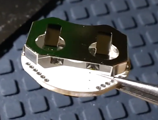
A soldering trick for the coin-cell battery holder
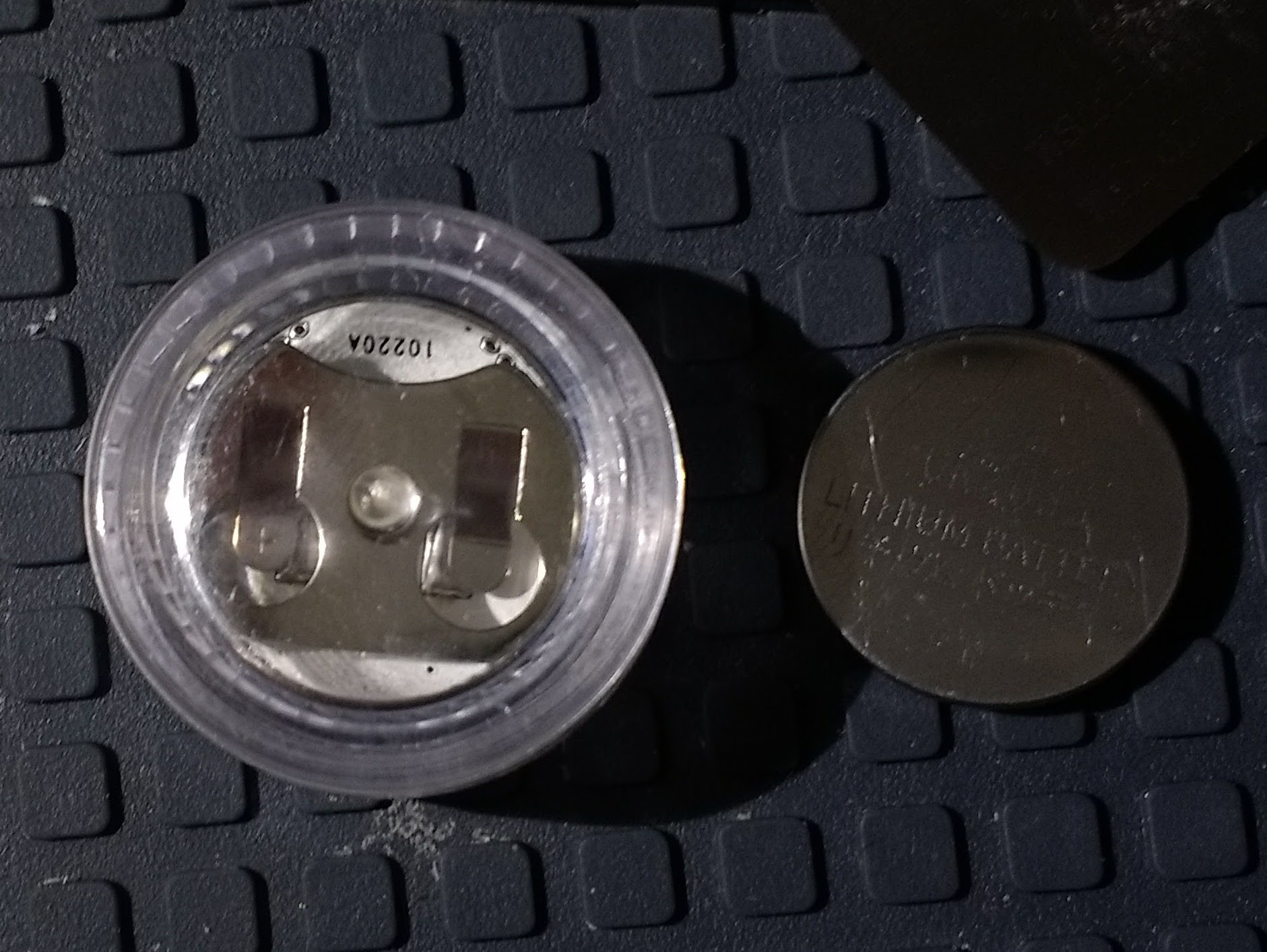
The only component on the back of the PCB is the battery holder.

The battery holder only connects the positive side of the battery. Lynx, the maker of this battery holder, specifies that almost the entire side of the board under the battery holder should be a flat contact for the negative side of the battery. With a 2-layer PCB, this would make it impossible to make all necessary connections without going around the battery holder area, which would mean the PCB should be much larger than the battery. To avoid this issue, I only designed two narrow strips as battery contacts on the PCB, but flooded them with solder to create a mound and allow a good contact with the battery. The battery rests on the mounds and doesn't contact the rest of the PCB, which is also covered by the solder mask, as long as the vias are covered. The battery holder has to be hand-soldered last. On this prototype I'm using the surface-mount version of this battery holder, but I've already changed the next prototype's design to the through-hole version to ensure a stronger attachment to the PCB.

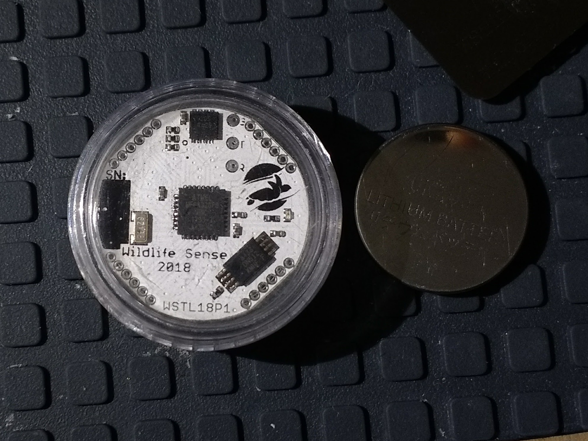
With all components assembled on the board, the WSTL18 fits snugly in a 3ml acrylic screw-cap vase.

The connectors on the bottom-right are the six AVR in-system programming lines. For now, I'm using six narrow cables to bridge my Atmel-ICE to them. In the long term I plan to create a special connector but may redesign mCU programming options entirely.
I programmed a simple blinking program as an initial check that the board is operational and it's working just fine using the real time counter.
 Nikos
Nikos
Discussions
Become a Hackaday.io Member
Create an account to leave a comment. Already have an account? Log In.