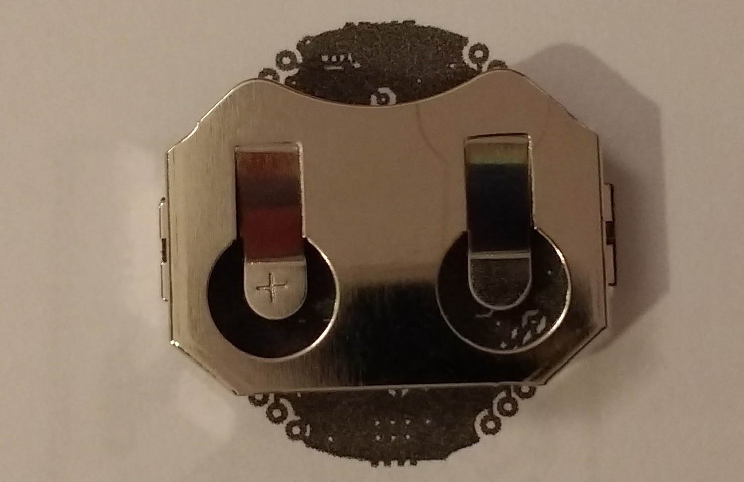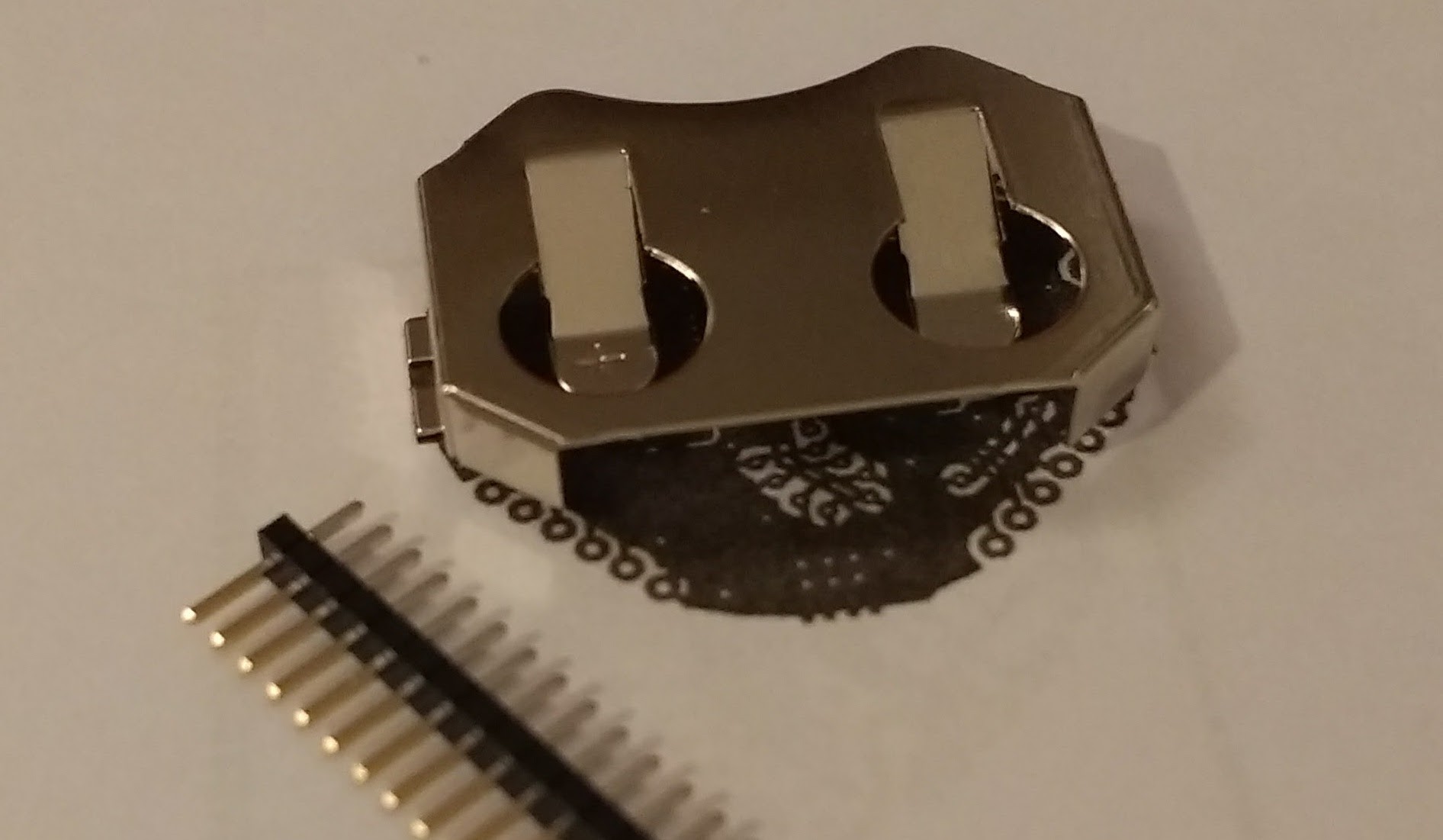
Last weekend, I ordered parts for the first prototype from Mouser and PCBs from Seed Studio. I also ordered a stencil for the top side from OSH Stencils. The parts arrived first, and while waiting for the boards I made a print-out to verify the battery holder fits well on the circuit board.
I opted to use a CR2032 battery because it's a good combination of size, capacity, and low-cost availability. The BAT-HLD-001 holder by Linx offers smallest footprint and by far the lowest price between holders for this battery. I've placed it on the bottom side of the board, so I'll have to assemble the device's top side first and then solder the battery holder on the bottom.
The battery holder attaches to the board with SMD pads, but on the next prototype I'll use its available through-hole version (Linx BAT-HLD-001-THM). That one will be easier to hand-solder, will allow slightly smaller board size, and will have a stronger hold on the board, which can help since the device will be handled during battery change and data transmission.
The battery holder is the largest part by far and alone defines the size of the board. All other parts can easily fit on the other side of the board.

The next smaller available battery that's between 2.7V and 3.3V is the CR1632 at 140mAh, which isn't bad and saves 4mm. But changing to this battery would have a few drawbacks: the cheapest battery holder for that size is €0.30 more expensive than for the CR2032 and batteries aren't cheaper. You also can't find a CR1632 at a corner store, but you can find a CR2032 almost everywhere.
Most importantly, I currently don't have a reason to switch to a smaller battery because the CR2032 will fit in the dirt-cheap case I've selected, and a smaller size of that type of case isn't available. I'll discuss the case in my next post.
A final word on this battery holder and my design: In my previous post I discussed making 14 MCU pins available near the edges of the board. I had to use 1.27mm (0.05") pitch holes, but at the time I didn't think that the battery holder would be right over the holes.

This only occurs on one side, as the other side of the holder is open for battery insertion. I've included the 1.27mm (0.05") header here to show that if it was inserted in the holes it would touch the holder, which is the positive battery pole.
On the other side, the headers wouldn't touch the holder but the battery would touch them while inserted or removed. To solve this problem, one can do one of the following:
- Don't use the pins, this is a temperature logger, not a development board. This will apply to most cases.
- Clip the header's underside after soldering and before placing the battery holder.
- Don't insert the headers all the way in. Keep them flush with the underside. This is probably the best solution.
- Don't use headers. Insert any cables directly into the pcb and solder carefully. Limits reuse.
- On the side seen above, bend the battery holder's flap. Will make battery placement a little tricky but won't solve the problem of contact during battery insertion/removal.
- Use a really thick PCB. Those are really expensive. Not a serious solution.
Also, in the rare case you will use this as a development board, use female headers, not male as seen here.
 Nikos
Nikos
Discussions
Become a Hackaday.io Member
Create an account to leave a comment. Already have an account? Log In.