Let's talk about magnets. Specifically, I don't think I've mentioned here how the period of rotation is being triggered.
Here's the first log where I showed off the (first revision) PCB design:
https://hackaday.io/project/27580/log/74559-holding-and-shipping
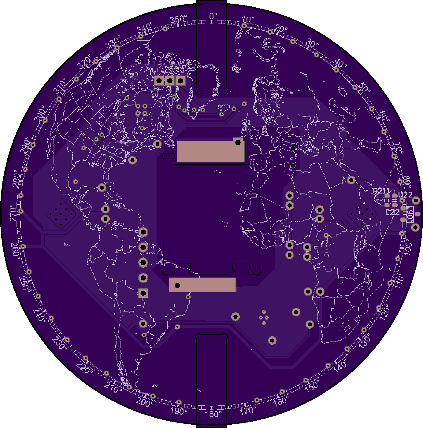
On the bottom of the PCB, you can see a footprint on the right side:

U22 is a Hall Effect sensor. The idea is that there is a magnet attached to the (stationary) frame, so it can trigger ever time that PCB edge spins past.
There are two issues with that, in general:
- Hall effect sensors are extremely slow. Most of the ones I checked out were in the order of 100ms to trigger and reset, and 10 Hz just isn't good enough!
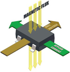
- All of the SMD packages sense magnetic fields perpendicular to the device, like so:

The first issued was solved by combing datasheets until I found something fast enough, and I did, the APS12205. The second issue was "solved" with a good bit of luck, as well as an additional problem that cropped up with this sensor.
As I hinted, it was actually quite difficult to find something that met my speed requirements, they're not common. But one of the downsides with this sensor, is that it is latching. That is, if you show it a north pole, it will hold its output high, even after you've taken it away. You need to show it a south pole to turn it off.
Solution:
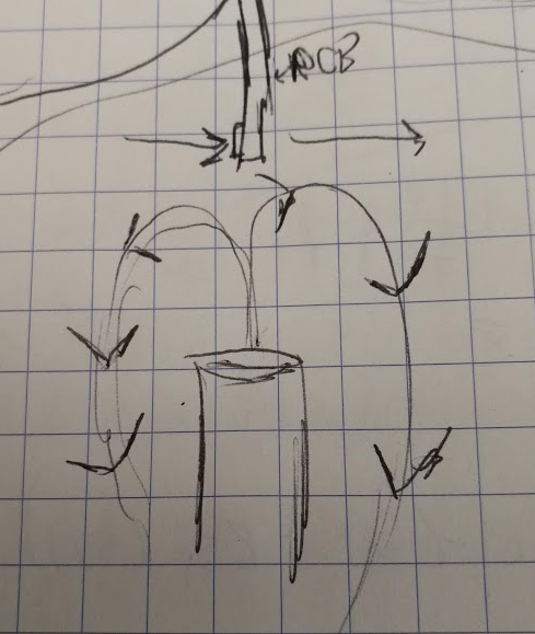
Taking a top view of the entire system, with the PCB rotating counter-clockwise:

Assuming the sensor is sensitive enough, and the magnet is strong enough, the sensor passes through two opposing magnetic fields throughout its rotation. It works! Potentially problem, avoided through good fortune.
While writing this log, I stumbled across an article (from 2003!) talking about a Hall Effect sensor with something that called an "integrated magnetic concentrator". Note to self, look into this for a project of some sort, it looks rad.
 Jarrett
Discussions
Become a Hackaday.io Member
Create an account to leave a comment. Already have an account? Log In.