Jarrett
-
Firming up the code
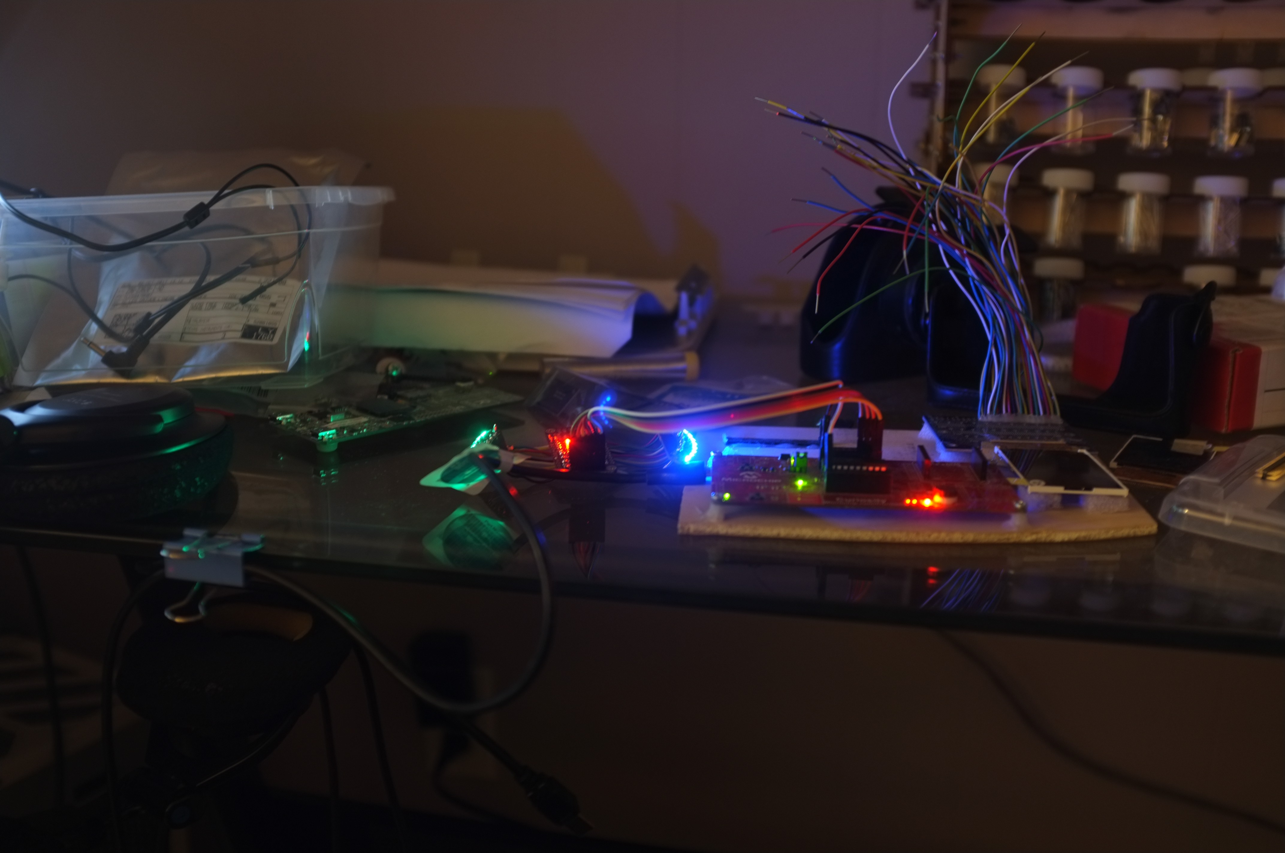
11/28/2017 at 03:51 • 0 commentsMy test jig is becoming invaluable, as I wait for more materials to arrive on the slow boat from China.
Project files are being posted here as I go, for those that missed it.
It makes my workbench look like an 80s cyberpunk fantasy.
![]()
The Python tool I've written to convert images to a POV-friendly format has been great.
Give it a command like:
python convert.py -i World_map.png -f c -v -c blueMap -x 152 -y 20 -o blueAnd it spits out generated C code, CSV files, or images after conversion. For more info, type:
python convert.py --help
It'll print out a handy menu of all the options.
The C generated output gets stored as a big chunk of memory and transferred out via SPI to the LED controller. Interestingly, the compiler chokes at any more than 6080 bytes of contiguous memory, even though it only uses up 78% of total memory. That'll be a memory paging issue, but I think it'll be fine. That is two displays (green and blue), 20 pixels high, and 152 pixels around.
For my test jig, I did much smaller - 10 pixels high and 50 across, and then waved it back and forth in front of camera a bunch.
![]()
Hey... that doesn't look like anything familiar.
Oh wait. No, I guess that's about right.
Here's the original:
(Greyscale values inverted because green must be 0xFF)
The final
Version at 20 pixels high will look more like this:
Recognisable, but it would still be nice if it were finer. Maybe revision 2.
-
Scrap it and do it again
11/10/2017 at 18:39 • 0 commentsI hinted in the previous log that there were some changes in the pipeline.
My CAD drawings use thinner acrylic than the stuff I actually ended up using. This, in addition to deficiencies of the design, led to some issues that require another revision.
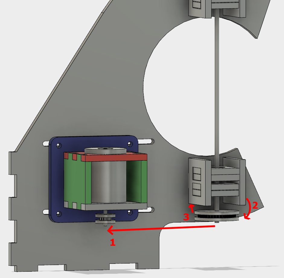
Here is the current design:
![]()
Due to the acrylic sizing, the bearing blocks on the right have a fair amount of slop. This isn't helped by cheap bearings, either. For the initial startup, the driven shaft goes all the way to the top set of bearing blocks, preventing the cantilever effect from causing issues.
As soon as that was sliced to hold the PCB, however, the cantilevering got much worse.
All three pieces of acrylic that make up each pulley are thicker, leading to all tolerances being a little tighter than how it looks in the design. When the pulley is on and tensioned, the forces are pulling the driven shaft(1). That's causing the shaft to cantilever towards the motor(2). When that happens, the sidewalls of the pulley start rubbing the bearing block(3), in addition to causing a ton of vibrating as the PCB is off-centre.
So that means that as soon as my PCB was actually attached, the system was hard to start, unstable when it did, and then high enough friction that my motor burned out.
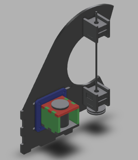
So it's back to the drawing board, for part of it.
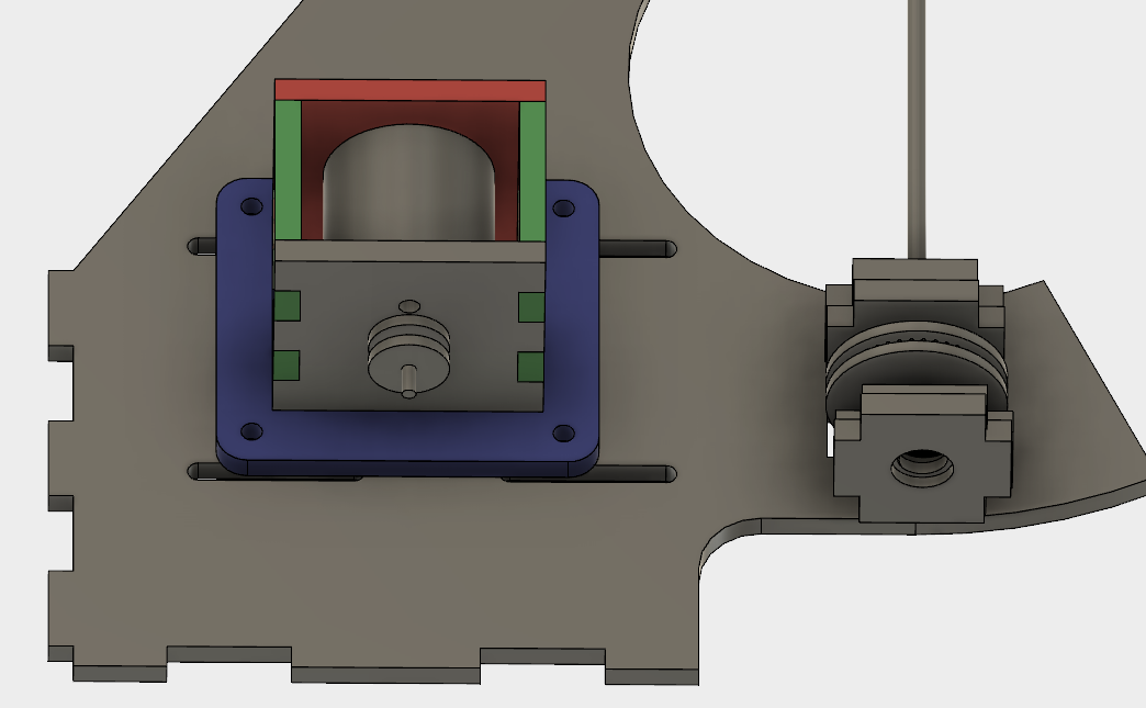
![]()
In this rearrangement that took all of 30 seconds, it should be easy to see what changes need to be made. The motor carriage will be shifted up a little, to allow the pulley to rest in between two bearing blocks. This should completely eliminate any cantilevering, unless the shaft itself is bending(which would be a Bad Thing).
Additionally, instead of trying to sandwich bearings with acrylic of the wrong size, I'll rest them in an open hole, held in by shaft collars at the appropriate places. That'll make more sense when I clean up the design.
-
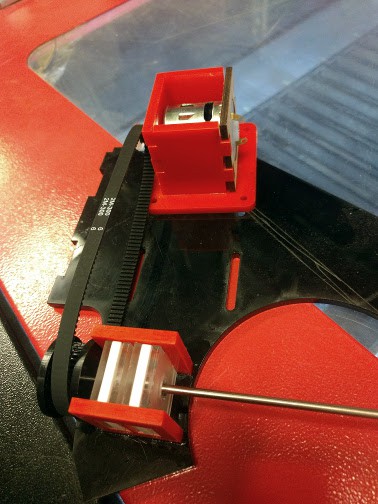
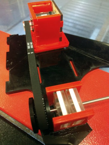
Spin up and first fit
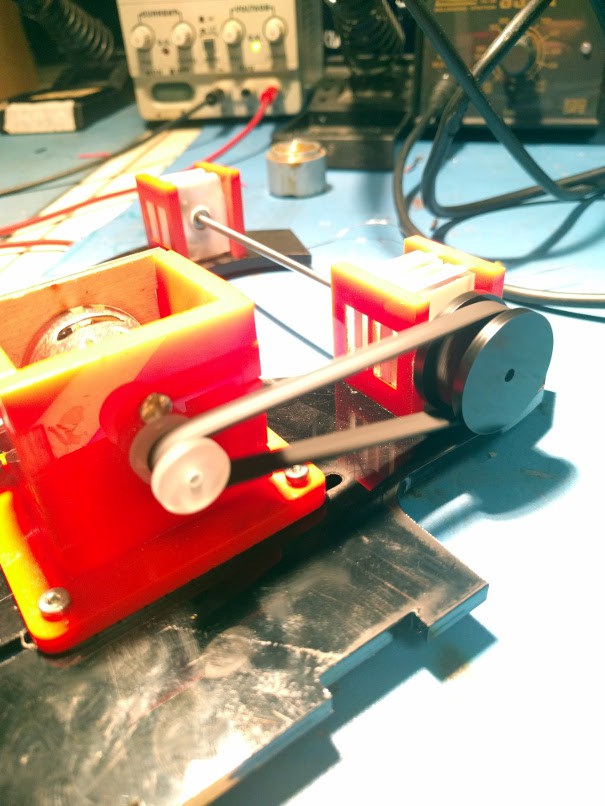
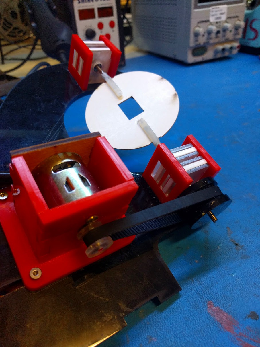
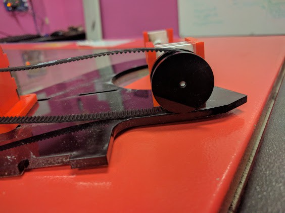
11/08/2017 at 19:14 • 0 commentsWhen we last left our intrepid hero - I mean the laser cutter, obviously - we were waiting on properly sized belts. I have received and installed one and spun up the machine. 200mm was a good size. It works, in this configuration!
![]()
The motor draws about 10.5W, and seems to go at a good clip. I should measure it at some point.
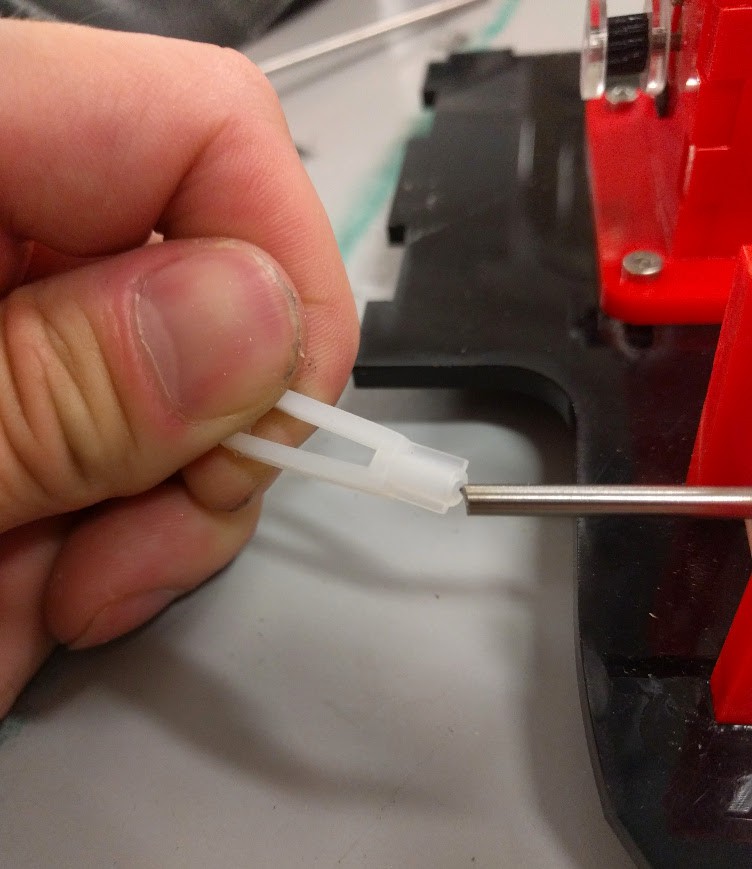
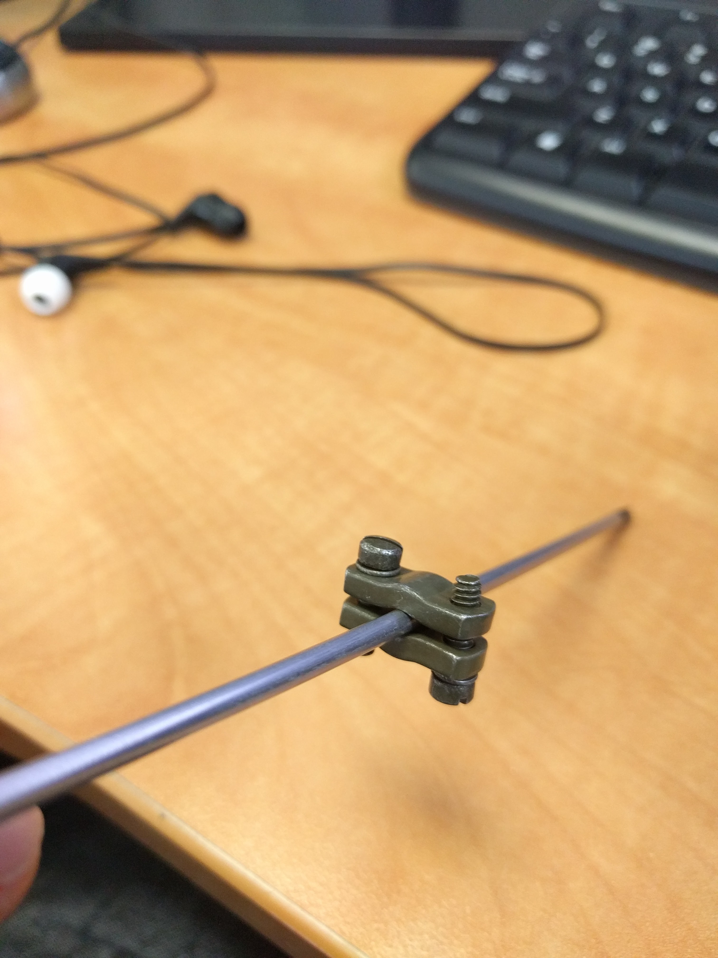
I still haven't found a silver bullet for my PCB coupling issues. The goal for today is to attempt one of the possible methods and see if it works. It wasn't written in the previous log, but I also picked up some nylon RC clevis pins. The bore is smaller than my 3mm shaft, however, and I couldn't find anything more appropriate.
![]()
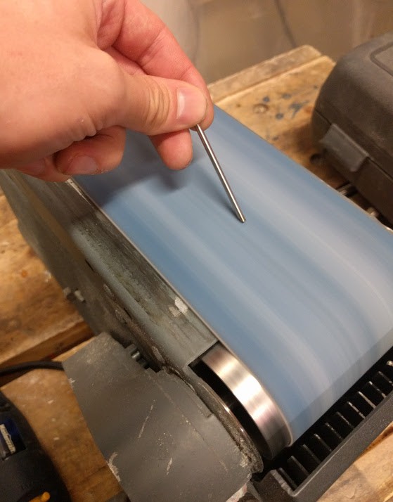
Instead of finding a 3mm drill bit and drilling it out, here's a neat trick that's much more versatile:
![]()
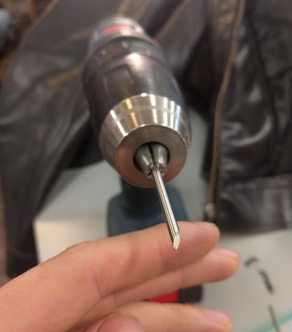
By grinding a flat onto hardened rod, you can turn it into very mediocre drill bit, with exactly the required diameter.
![]()
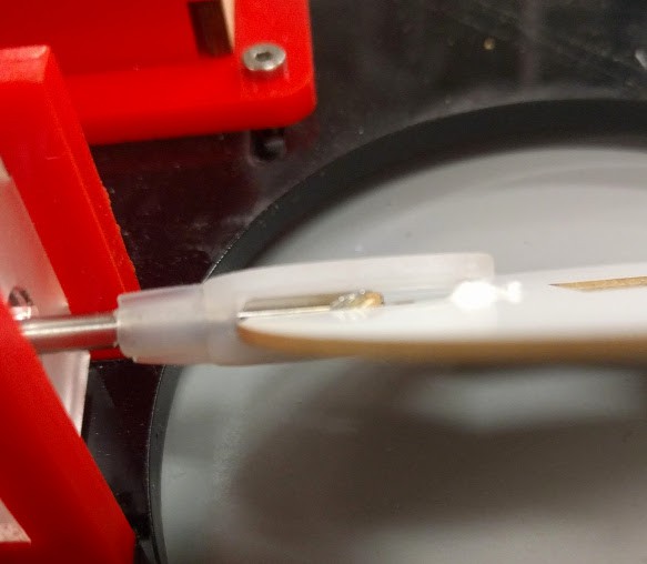
And then you can drill it into the nylon pins.
![]()
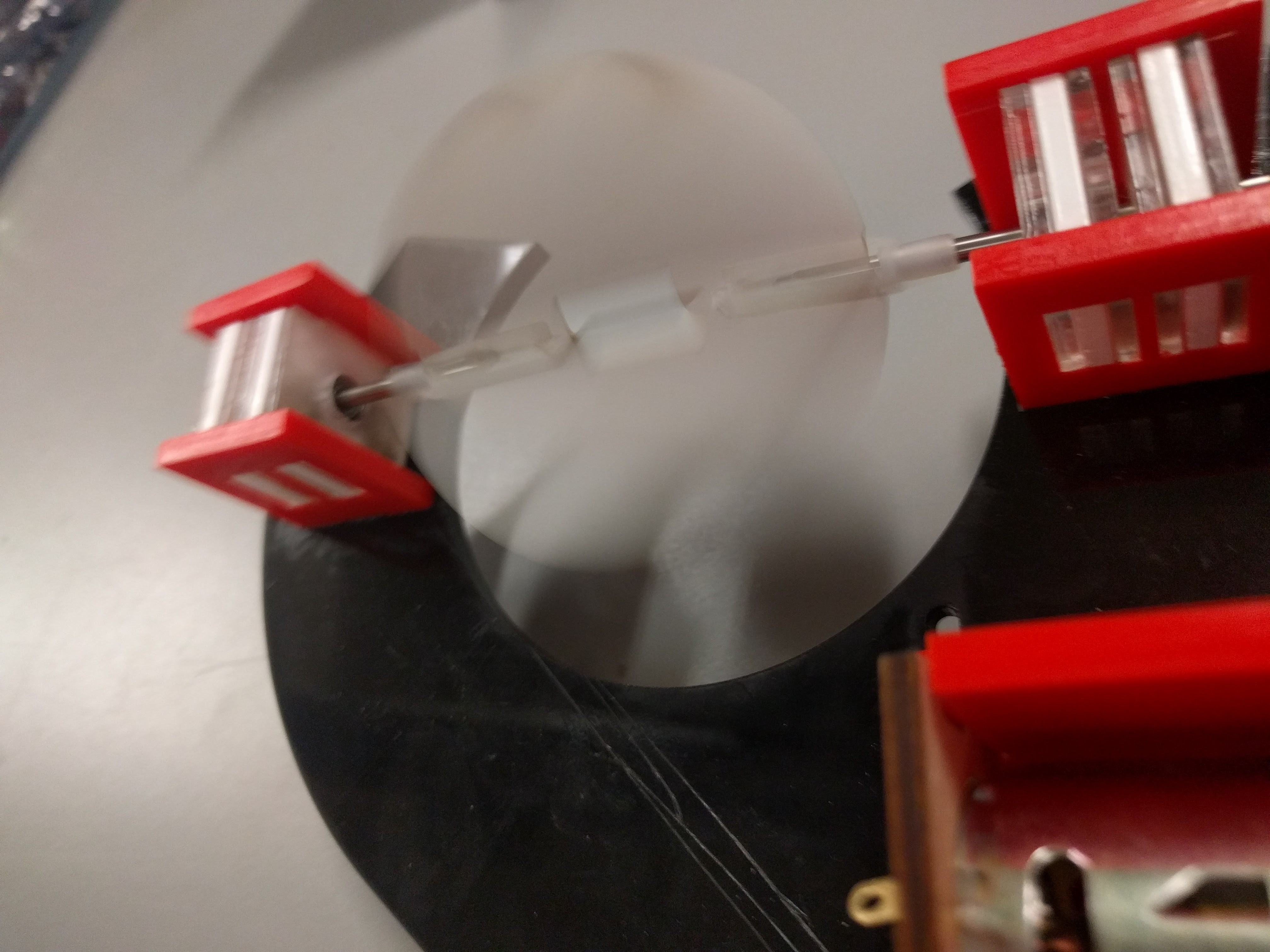
Here's the machine, completely assembled. That cardboard disc is a stand-in for my PCB, with a pretty similar thickness.
![]()
Spun up:
![]()
Yeah, I'm quite happy with the speed.
But it's now time to scrap this revision and rebuild it from scratch. Stay tuned!
-
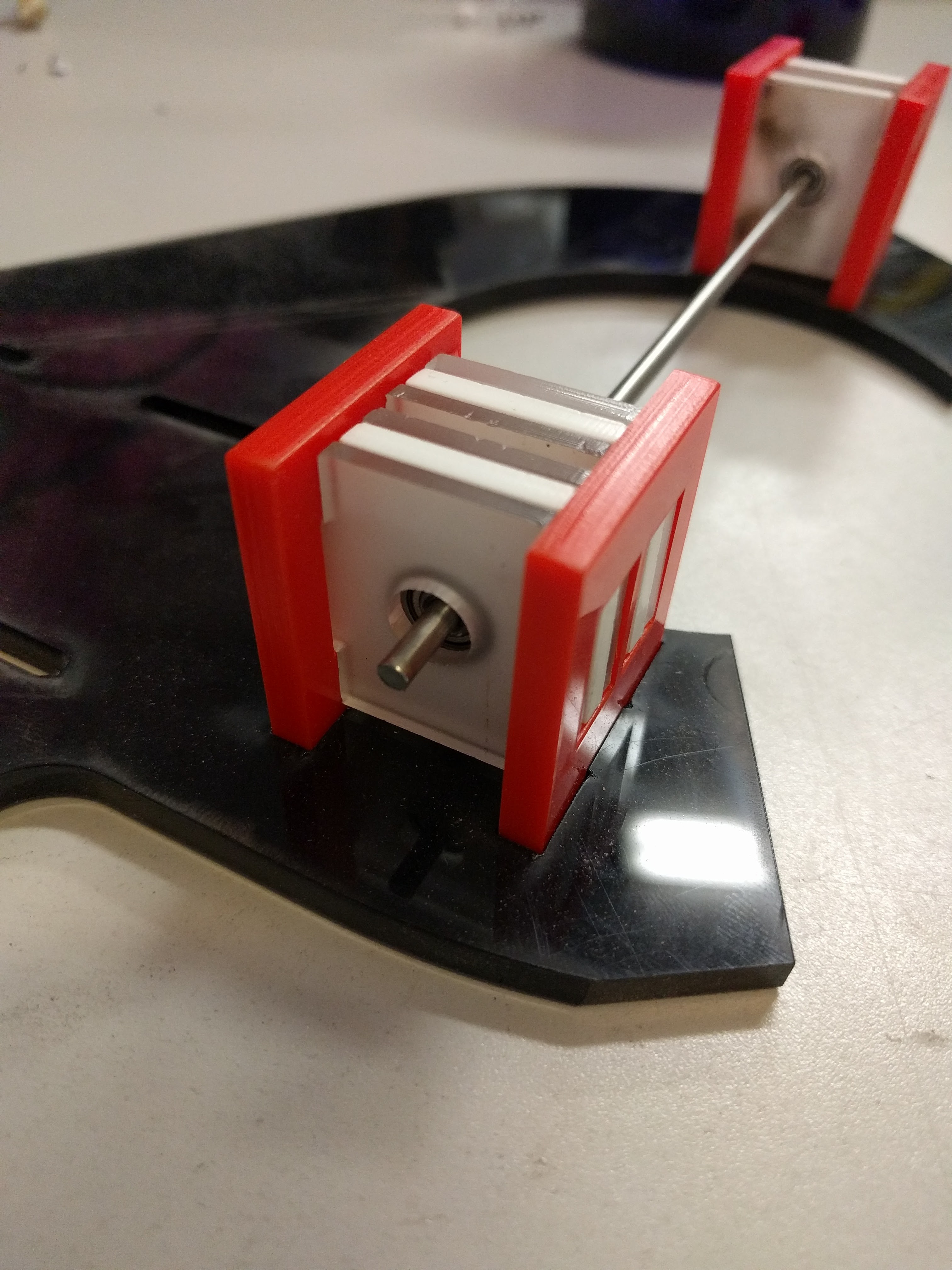
Hjalp! Mechanical plan and call for discussion
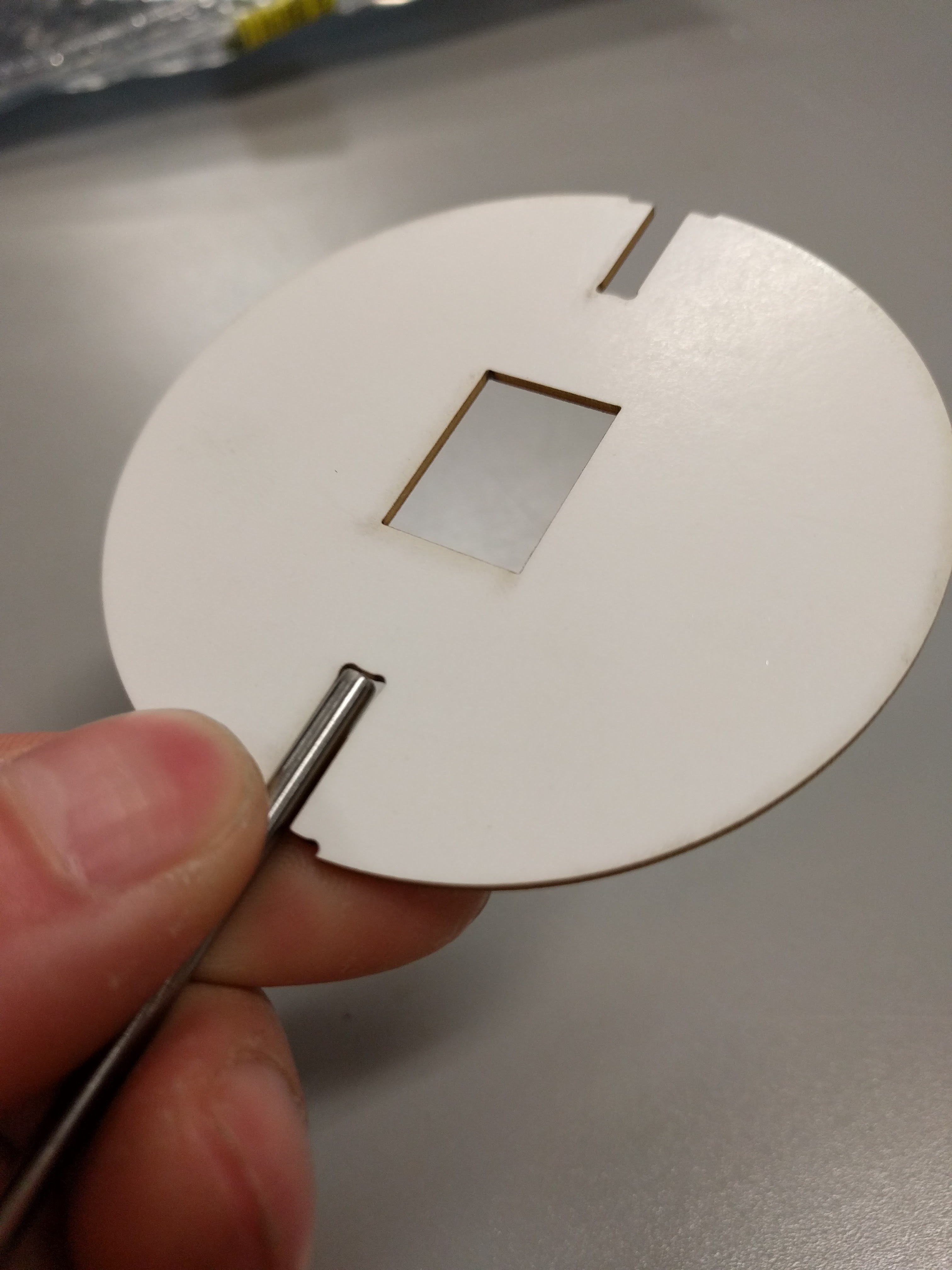
11/05/2017 at 22:14 • 4 commentsHere's a mock up of the PCB. It'll be spun axially by 3mm shafts on the top and bottom.
![]()
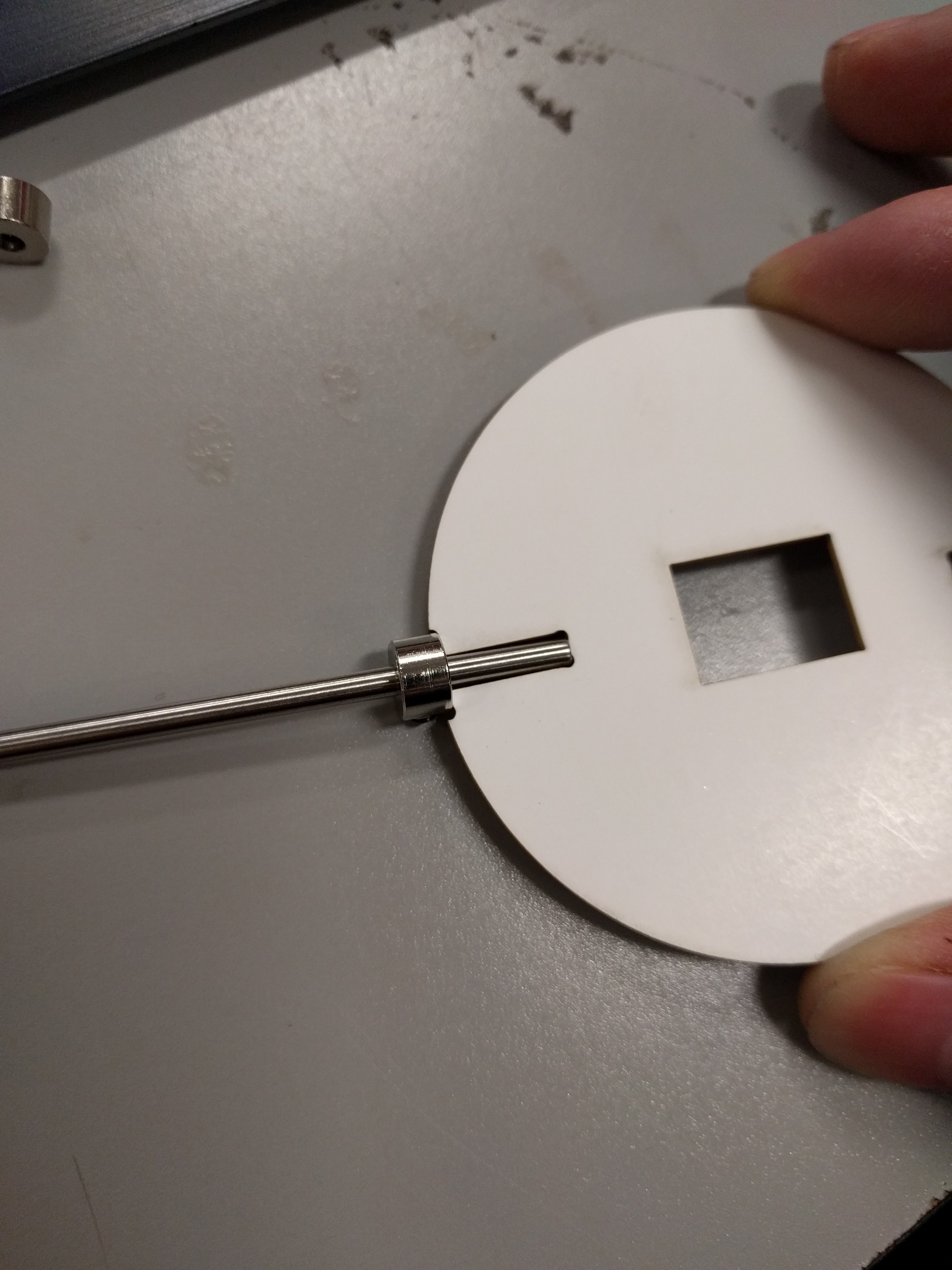
And herein lies the second question:
What's a good method for affixing the shafts to the PCB?
![]()
The current working plan is to use a shaft collar with a 1.6mm thick slit carved into the face to hold the edge of the PCB.
This method has a couple problems:
How do I cut the slit?
It's not an off-the-shelf solution.
There are a couple other solutions I've been toying with:
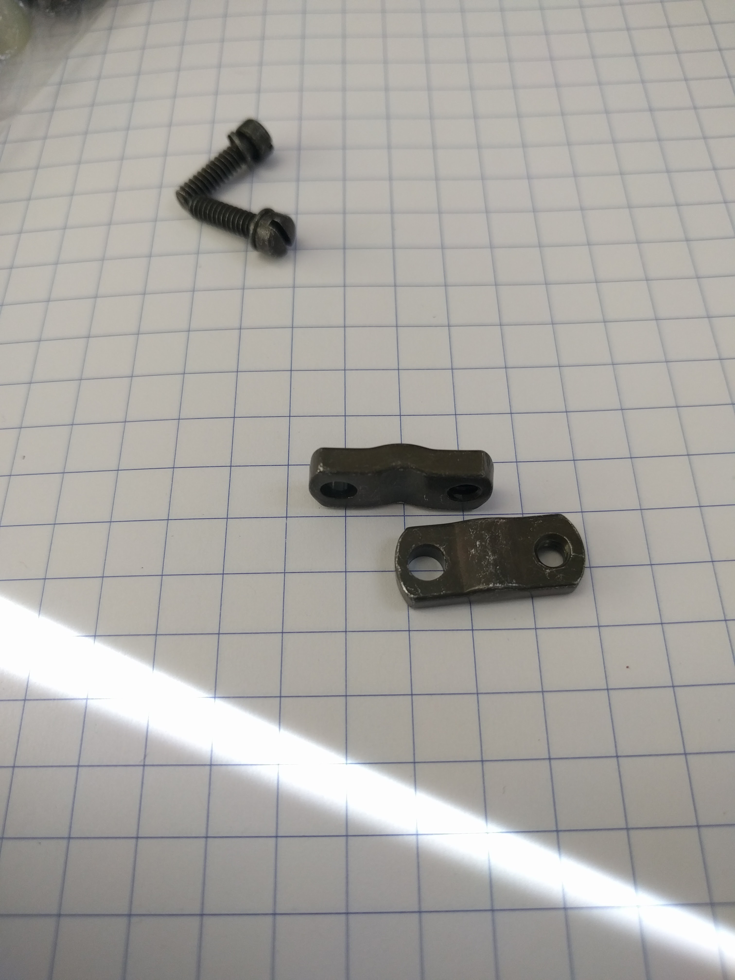
![]()
![]()
These are two identical plates, clearance holes on one side, and threaded holes on the other.
I don't know where to get them, or what they're called. Colour doesn't matter, but shape is important. These ones, and others I have seen, come as cable clamps for some DB15-style connectors.
Because they're just support pieces for connectors, however, they don't seem to be able to be purchased individually, or have dimensions associated with them. $4 for the entire package is cost prohibitive, too.
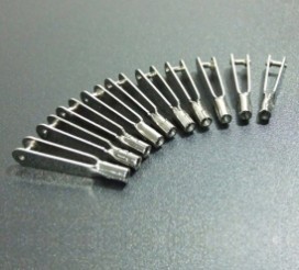
Another possible method:
![]()
Hobby RC plane clevis pins.
There are a few issues with that, too.
There isn't really anything that fits both the shaft and the PCB thickness. They're cheaply made and inconsistently sized. They're also too long and eat up my vertical board space.
So what say you, internet? Any suggestions? Alternate ideas, or good sources for things?
-
Here be code
11/04/2017 at 02:33 • 0 commentsIf you don't need or want a simple C driver for this chipset, I'd skip this post!
#define OE          LATBbits.LATB5
#define XLAT        LATCbits.LATC2

//12 bits per channel = 1.5 bytes * 24 channels
#define TABLESIZE 36
#define CHANNELS  24

void main(void)
{
    unsigned int i;
    uint8_t mapInc = 0;
    uint8_t blob[TABLESIZE];

    while(1)
    {
        //Zero out buffer
        for(i = 0; i < TABLESIZE; i++) {
            blob[i] = 0x00;
        }

        //Colourspace is 0xFFF levels
        //Dividing/multiplying by four to speed up the fade
        for(i = 0; i < 0x1000 / 4; i++) {
            setChannel(blob, mapInc, i * 4);
            LEDMap(blob);
        }

        mapInc = (mapInc + 1) % 24;
    }
}
void setChannel(uint8_t *blob, uint8_t channel, uint16_t value) { uint8_t lvalue; uint8_t rvalue; uint8_t newVal; uint8_t byteAddr; if(channel % 2 == 0) { byteAddr = (channel * 3) / 2; lvalue = (uint8_t)(value & 0xFF); rvalue = (uint8_t)(value >> 8); *(blob + byteAddr) = lvalue; newVal = (*(blob + byteAddr + 1)) & 0xF0; newVal = rvalue | newVal; *(blob + byteAddr + 1) = newVal; } else { byteAddr = (((channel - 1) * 3) / 2) + 1; lvalue = (uint8_t)(value << 4) & 0xF0; rvalue = (uint8_t)(value >> 4); newVal = (*(blob + byteAddr)) & 0x0F; newVal = lvalue | newVal; *(blob + byteAddr) = newVal; *(blob + byteAddr + 1) = rvalue; } } void LEDMap(uint8_t *blob) { uint8_t data = 0; XLAT = 0; for(int i = TABLESIZE - 1; i >= 0; i--) { data = *(blob + i); SPIWrite(data); } XLAT = 1; __delay_ms(1); XLAT = 0; }I cut out all the PIC initialisation stuff, but the only gotcha there is that the SPI must transmit on the active to idle clock transition.
-
Mini Driver
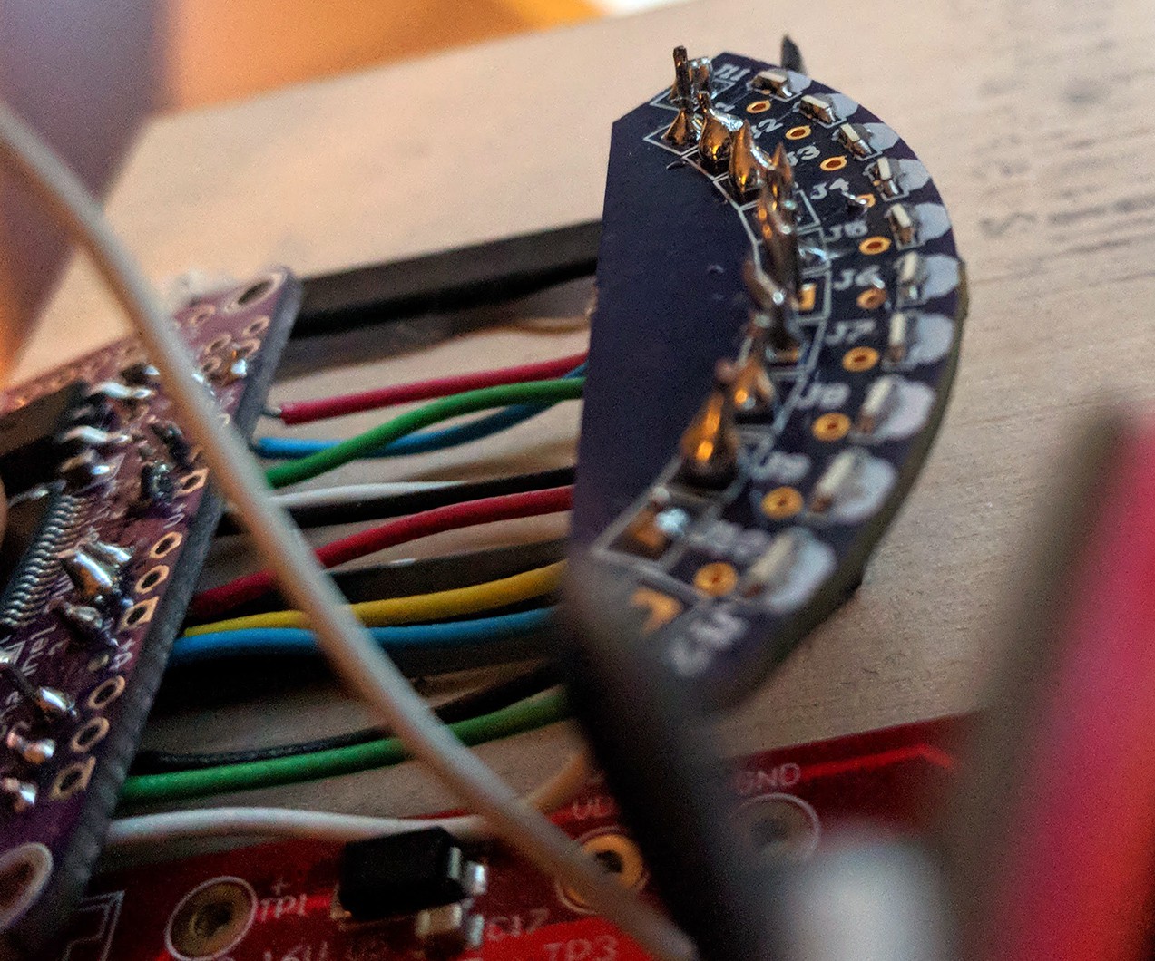
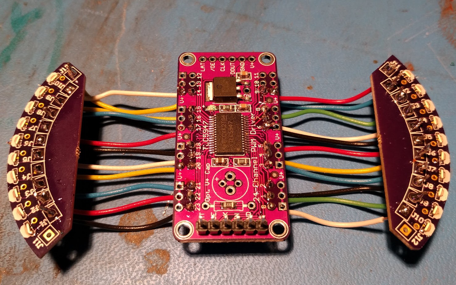
11/03/2017 at 00:38 • 1 commentAs described earlier, I spun a small test board through @oshpark with the same diametre and side-mount LEDs as the final goal.
![]()
I've now written a driver for the TLC5947 in C and tested it out. The excellent @Microchip Technology Curiosity board was the closes dev board within arm's reach, so it got the goods. Guess I'm using a PIC for this project! I hadn't decided until now.
It's probably a good idea anyway, I'm more comfortable with the low level peripherals than with the other option I was considering (ARM Cortex M3).
But it blinks!
![]()
It's pretty efficiently written, I feel pretty confident in good resolution being possible. As I write this, I realise that I haven't done a full stress test of all the LEDs in the array turning on and off in rapid succession. That'll give me some indication if my voltage lines are sagging. I'll post up the driver code in a bit, too. It's fairly simple.
-
Tech Demo
10/25/2017 at 18:34 • 0 commentsAfter some catalog-hunting, I settled on the TLC5947 for my LED drivers. It's an SPI-controlled PWM LED driver with 24 channels. I'll need two of them, but I'd like to get a feel for how they work before I commit to a design.
Here's a $10 technical test, with an Adafruit-designed breakout and minimal OSHPark boards. It's using the same side-mount LEDs in the same orientation as the final design, and I'm pretty happy with them.
Only issue is that I have no idea what colour each package of LEDs is, they're labelled in Chinese!
![]()
For anyone that wants to make the test boards, my "miscellaneous" PCB repo is here:
https://github.com/JarrettR/PCBs/tree/master/15-RingLED
It costs $6.10 for three.
-
Hmm.....
10/09/2017 at 08:09 • 0 commentsCheck out my tensioning slots on the base plate:
That's a pretty common way to allow a builder to slide the pulleys back and forth until tension on the belt is juuuuust right.
But wait, what's this?
![]()
![]()
That only works if you calculate your belt length right! Way off the rails and there's still lots of looseness!
Turns out, I had it calculated for ~300mm on an older pulley design. But the old pulleys had to be reduced in size to clear the base plate:
![]()
New designs work out to be around 250mm, so I have a couple new belt sizes coming in that bracket that measurement. Bonus: I'm starting to build up a collection of sizes! The rapid prototypers' dream, the space-constrained apartment nightmare.
-
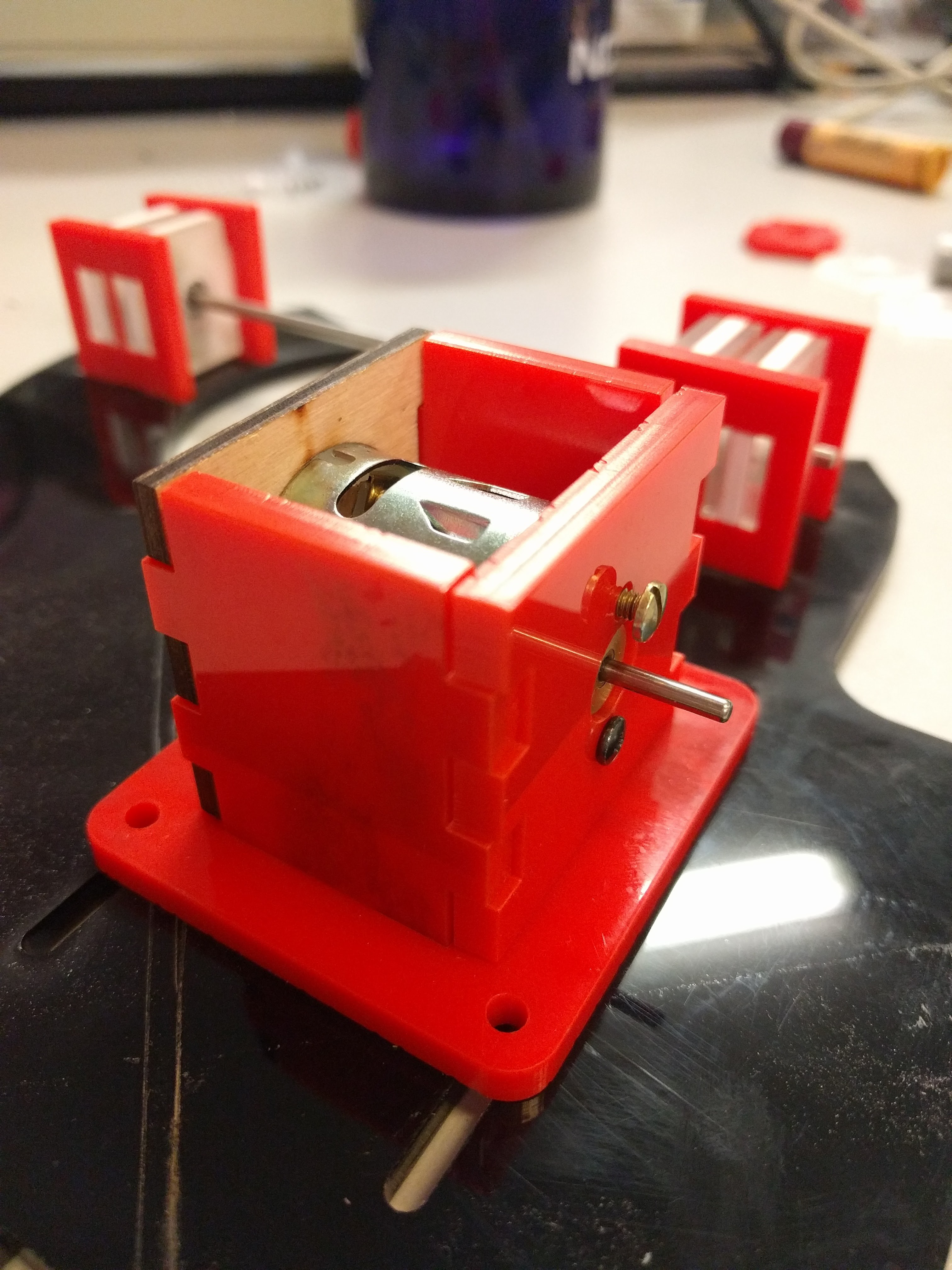
The Mechanicals
10/08/2017 at 23:01 • 0 commentsHere's the initial mechanical design.
It's totally a "throw together" laser cutter design, using mostly components I have on hand and scrap acrylic.
![]()
The design is very definitely sub-standard, in both form and function. The critical parts are locations of the DC motor output shaft, and bearings. The surrounding frame is totally unimportant, and will be replaced with something pretty when I've proven the mechanicals.
![]()
Yeah, this is entirely made out of scrap-bin materials. Upcycling!
A timing belt from the motor shaft will drive the main shaft, upon which the PCB is mounted. I was planning to finish laser cutting the timing belt pulleys too, but then some friends showed up and we started drinking.
Good times.
-
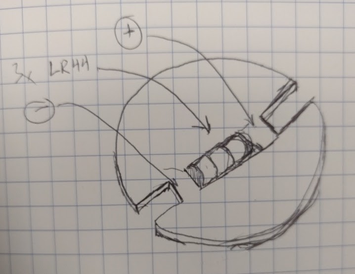
RFC: Battery Holders
10/04/2017 at 23:05 • 0 commentsAs mentioned in the previous log, I don't have a bespoke solution for batteries yet. This is the area that needs the most improvement at this time.
Currently, the working plan is to stack up 3 LR44 batteries in-line with the PCB, as shown. This has the advantage of being small, axially balanced, and in the right voltage range. That last point is not critical, as I could work with 3V, or throw a boost converter on there if the blue LEDs require.
![]()
My initial thought was to throw a wide zap-strap on there to hold the batteries in, and form some copper contacts on either end to make electrical contact.
This is janky and I'd like a better solution! Let me know if there are any. An off-the-shelf axially-mounted battery holder would be boss, but I don't think they exist.