 Øystein
So I did this mini project to learn a bit more about toolpaths in fusion and the use of different cnc milling bits. So I modeled a simple business card holder and started building toolpaths in fusion 360 cam module. Afterwards it look something like this:
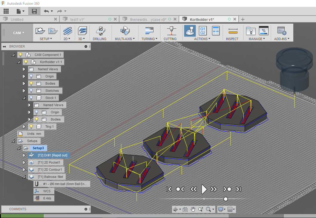
The yellow lines represents where the cnc spindle is moving in free air and blue where it cuts. This job consists of 4 toolpaths (jobs). 1 drilling holes to put screws in. This is to make shure that the sheet of wood does not move while the cnc is cutting. Second is the pocket holes. Third is the contour that cuts out the outline of the object and leave small tabs so that the piece still stays in place. he fourths is a contour that makes a fillet (round edge) on the edges on top of the piece.
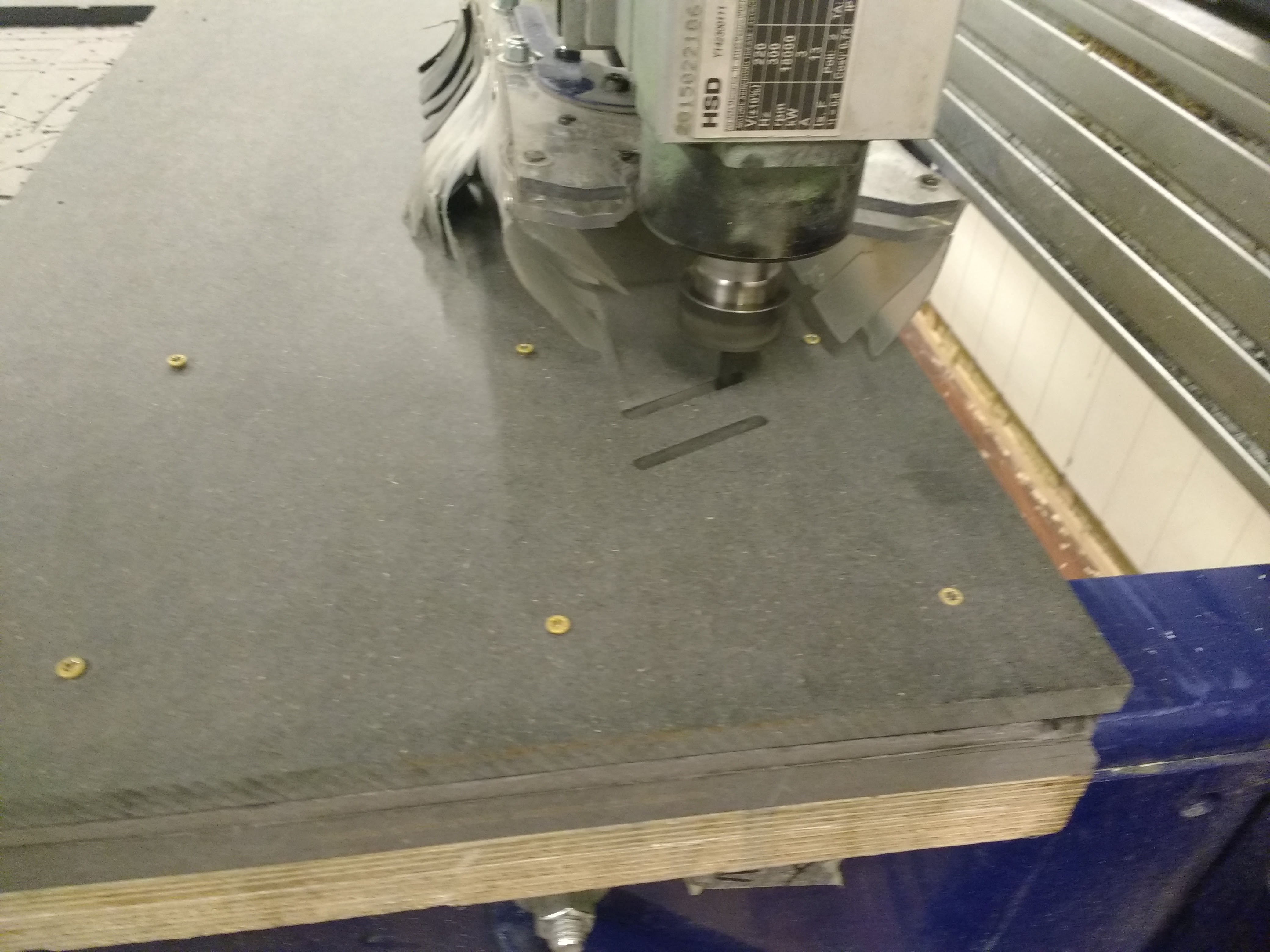
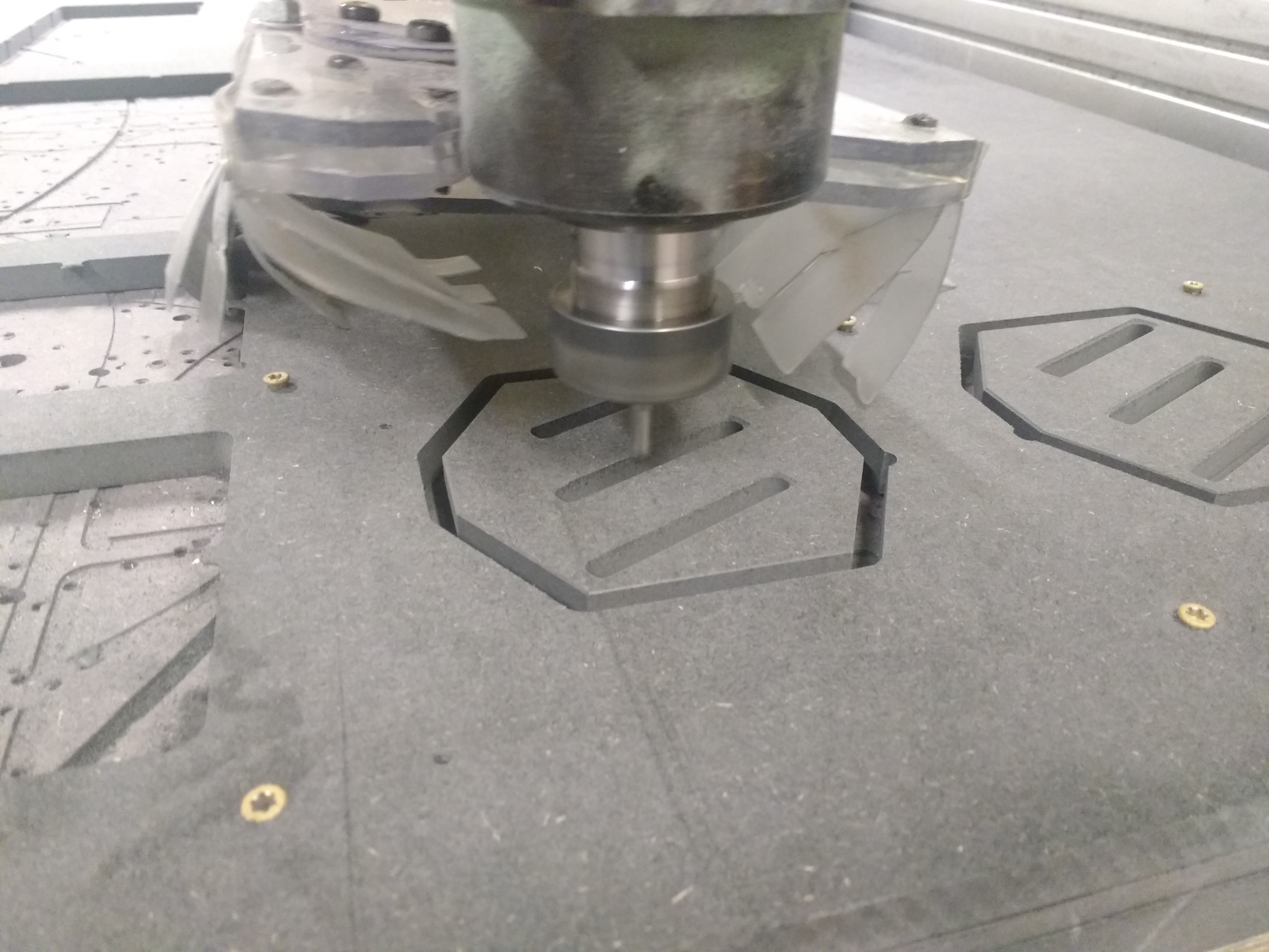
Here you can see the ballnose milling bit finishing the edges of the piece. A ballnose bit is a milling bit with a round tip primarily meant to make smoother edges.
 Aaaand done!
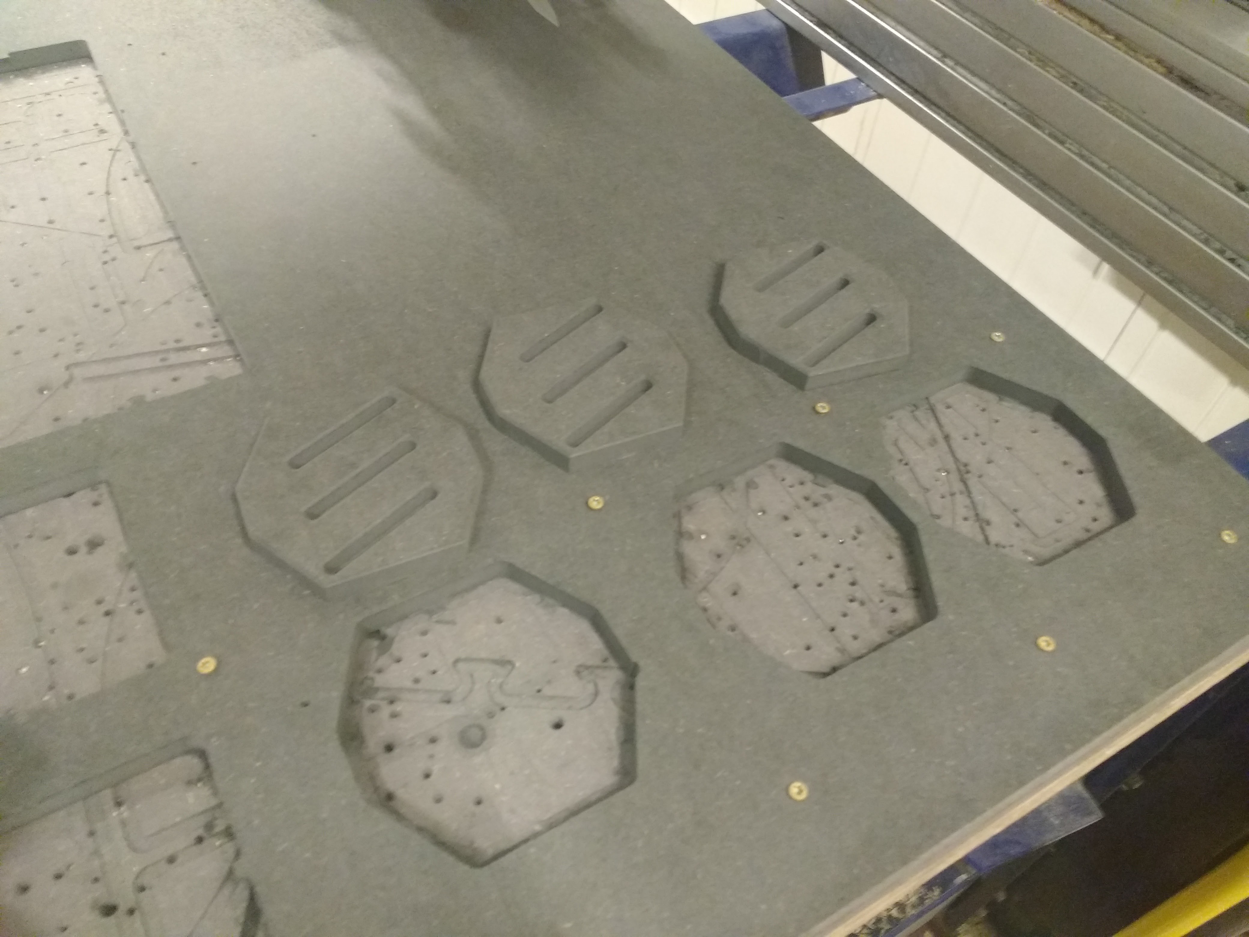
Discussions
Become a Hackaday.io Member
Create an account to leave a comment. Already have an account? Log In.