I used an Adafruit BLE Feather 32u4 as the microcontroller for this project. It takes care of Bluetooth 4.0 connectivity and hotswap-style LiPo charging all in a sleek 2" by 0.9" footprint, making it ideal for this application. I purchased special, shorter female headers (linked in the Components section) to mount my custom shield and keep the profile as low as possible. To sit snugly against the neoprene, I needed the bottom of the Feather to be completely flat, which would be impossible if I mounted the PTH header in the conventional manner. So, I trimmed the headers to be very short and used minimum solder for every pin, resulting in a flush bottom side. See the video for more details on this technique.

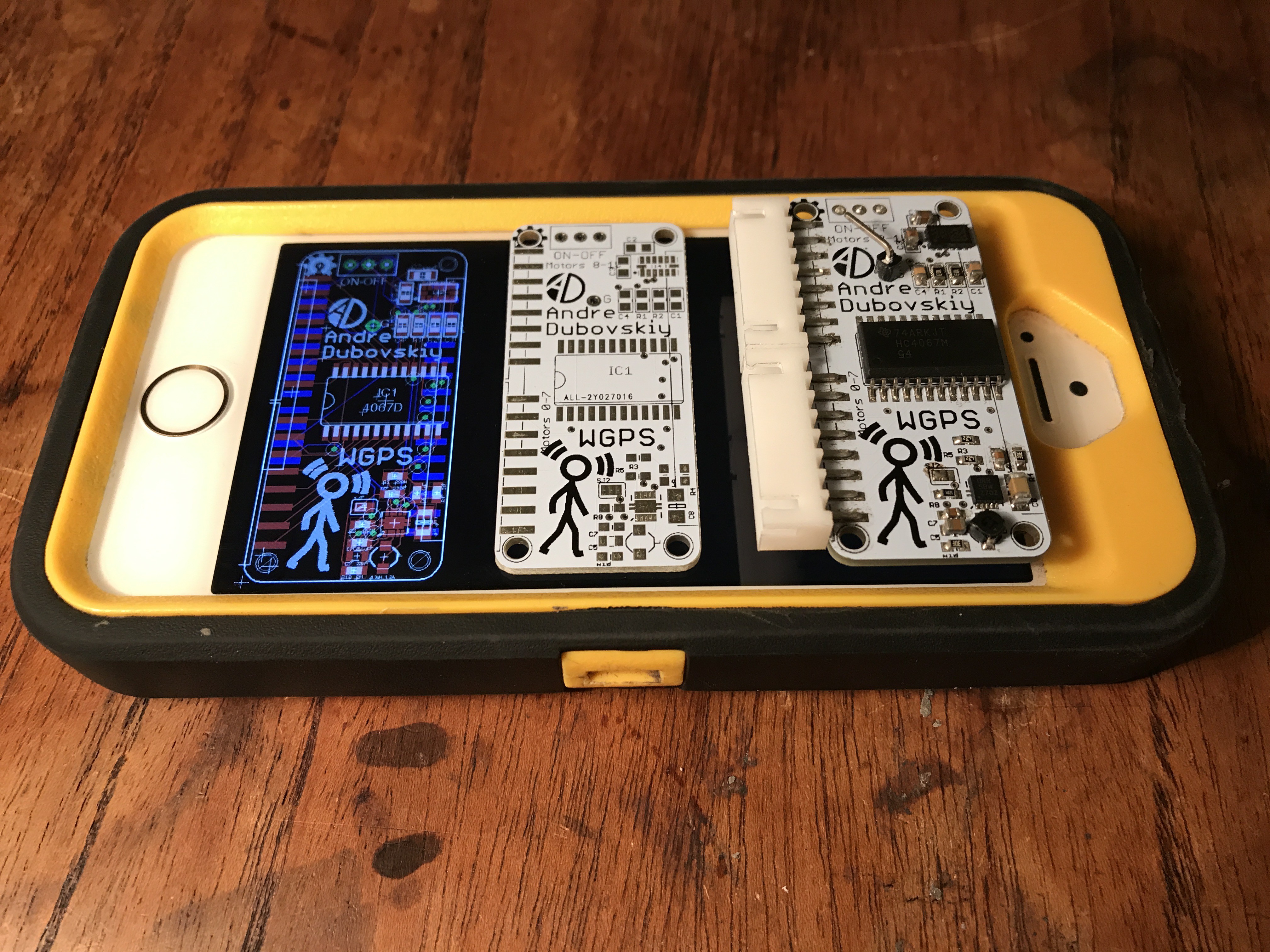
The shield was one of the hardest parts of the entire project. I designed my PCB in EagleCAD with two 8-pin JST plugs, LSM303DLHC tilt-compensated magnetometer, boost converter, and a 16-channel HC4067 demultiplexer from TI. For the LSM chip and boost converter I found open source PCBs from Adafruit and Sparkfun respectively, and integrated them into my design. I also ordered the corresponding PCBs, as well as a broken-out 4067 so I could play with all the parts on a breadboard to make sure they could be used the way I wanted. I added these PCBs to the Components section but keep in mind that all the components can also be purchased separately.
Many of the components were tiny and had QFN-like packages. Also, unlike Adafruit's "FeatherWings," I had to surface mount the headers to the bottom rather than with PTH, because otherwise I could not have broken out the female JST sockets to the side of the shield the way I did. My methodology here was inspired by this guy. I ordered the PCBs from allpcb.com. As far as Chinese fab houses go, these guys are very reliable. I paid a grand total of about $25 for ten 51x23mm boards, that arrived six days after I placed the order.
As soon as the boards came in the mail I began to eagerly assemble them. I used a solder paste syringe and tweezers to do all of the populating by hand. I don't think a stencil would have made the task significantly easier. When the board was ready, I used my hot air SMD rework tool to reflow the solder paste. On my first attempt, the boost converter didn't work. I think I may have put too much paste under the tiny TPS chip. Always use an absolutely minimum amount of paste for the teensy no-lead packages. Fortunately, upon my second try, everything was functioning. I could get sensor readings from the LSM chip with I2C and my motors were buzzing thanks to the 4067 demux and boost converter.
 Andre
Andre
Discussions
Become a Hackaday.io Member
Create an account to leave a comment. Already have an account? Log In.