 Marius Taciuc
The C++ software section responsible for calibrating the device is quite self explanatory.
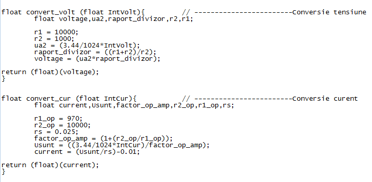
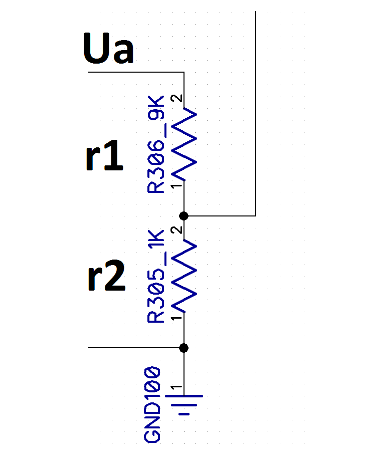
Adjust from software the values of the resistors you populated on your voltage divider, then measure the MCU voltage and replace this voltage for the ADC into the formula.
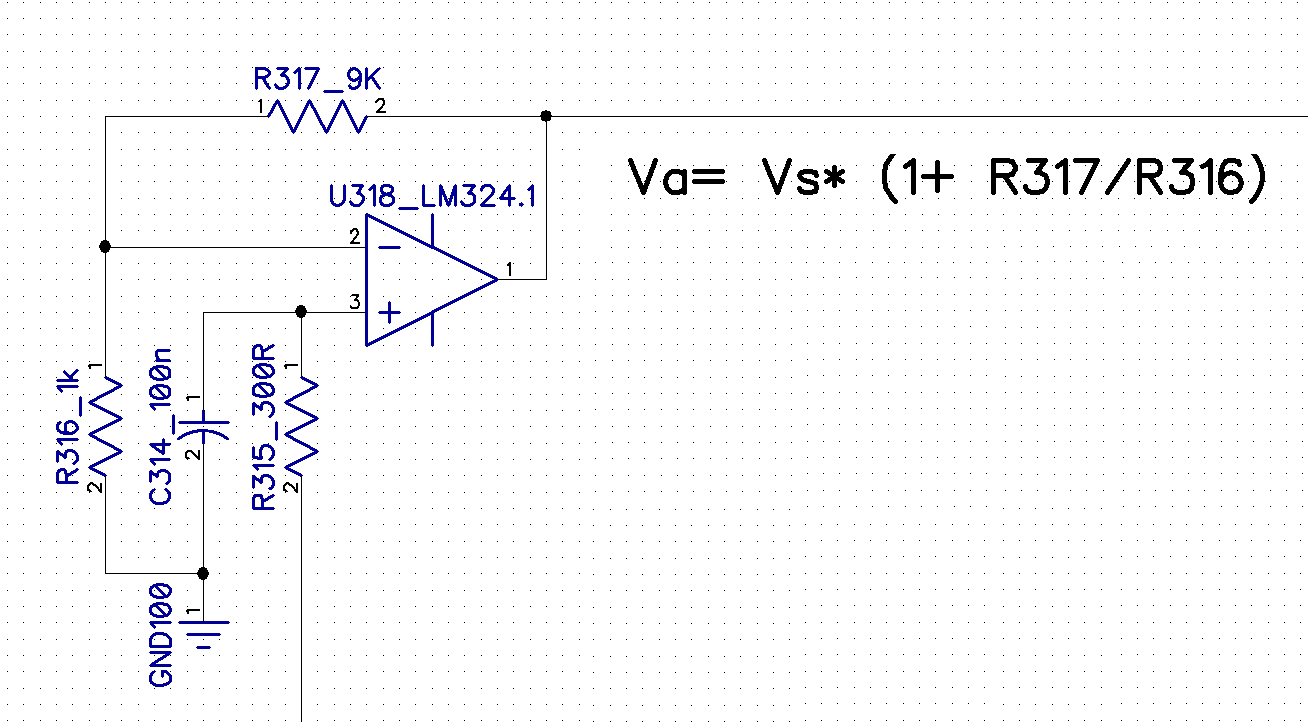
For calibrating the current reading, keep in mind that you can easily have some resistance variations on the shunt and this could be because of your solderings and because of the pcb design. So after you made sure you got the OpAmp resistors correctly declared and the ADC voltage, adjust the measurement from the shunt value. This is very sensitive and a simple change from 0.25 to 0.259 can mean almost 4%. It helps if you use a good calibrated multimeter that you might have around the shop to gain the actual value of the measured current. And since we're talking about multimeters and the accuracy of a good multimeter for calibrating this thing, I will take the liberty of attaching this review I made some time ago:
Discussions
Become a Hackaday.io Member
Create an account to leave a comment. Already have an account? Log In.