 JasMoH
After tweaking my solder setup, I got one of my three prototype boards to work. This one is populated with the AD8429 (variable gain amplifier) and a trip pot so I can get an idea for the gain necessary for my application.

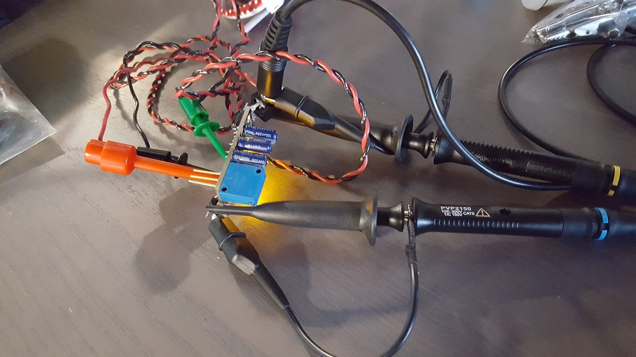
My totally low noise haywire setup. PC sound card on lowest volume stimulating a 440Hz sine wave for input.
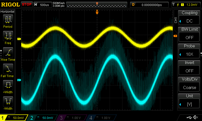
Results with a low gain applied.
Discussions
Become a Hackaday.io Member
Create an account to leave a comment. Already have an account? Log In.