 Bud Bennett
The inverter circuit appears to work as advertised. I was able to get the correct telemetry displayed on my Taranis transmitter. Here's the procedure:
I hooked up the inverter board to +5V, GND, TX3 and RX3 on the DYS F4 flight controller board. I also connected the inverter input to the smart port lead on the XSR-E receiver (the thin blue line). Here's the inverter next to the receiver.
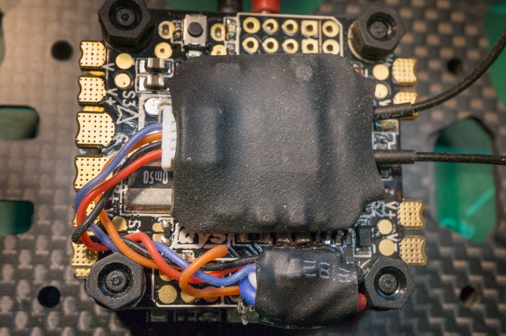
I then hot-glued the inverter to the flight controller board to reduce stress on the wiring. I attached the receiver with double-sided sticky foam tape. Both items are pretty small compared to the flight controller. Here's a side view of the stack:
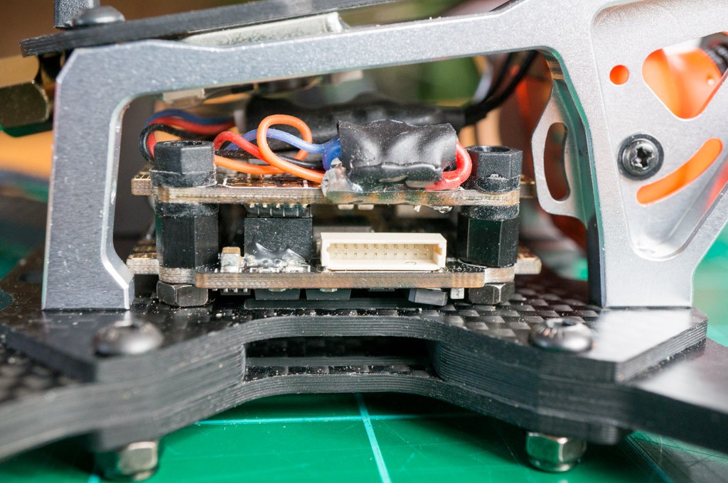
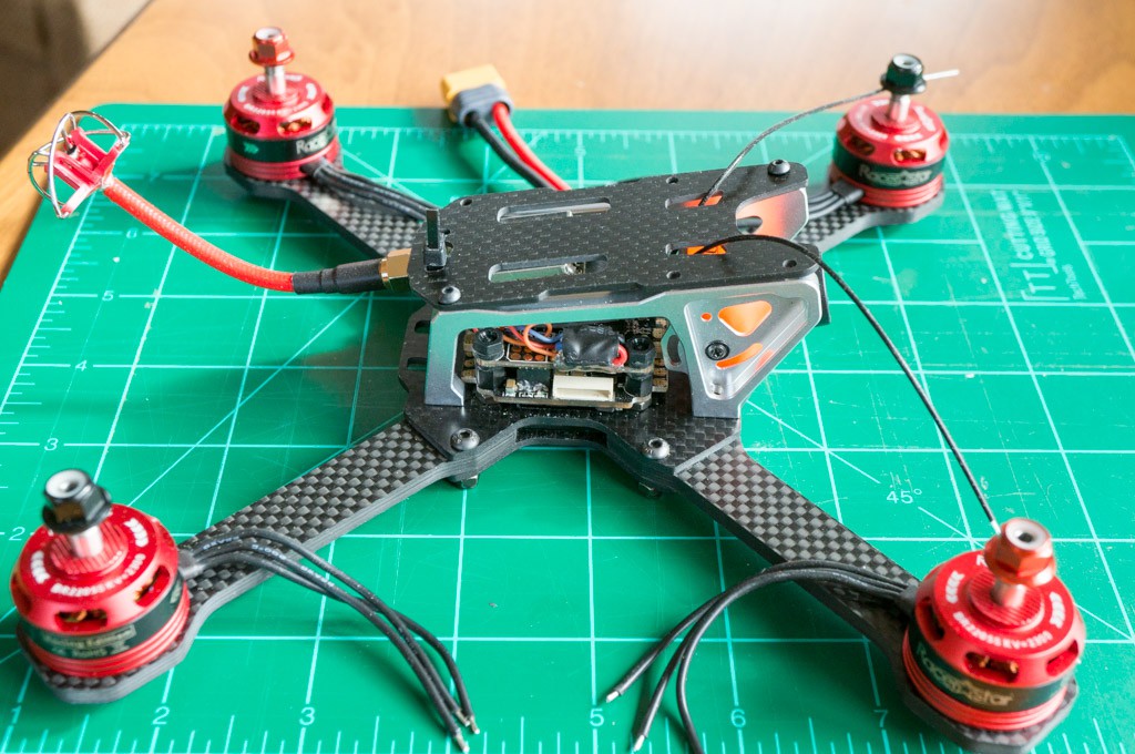
This quad uses a Transtek Frog Lite frame so there is very little room within the housing. Fortunately, everything fits fine. Here's a top view of the entire quad in a mock-up state (I'm waiting for some 20AWG silicone wire so I can hook up the ESC to the motors.) There's not much room.
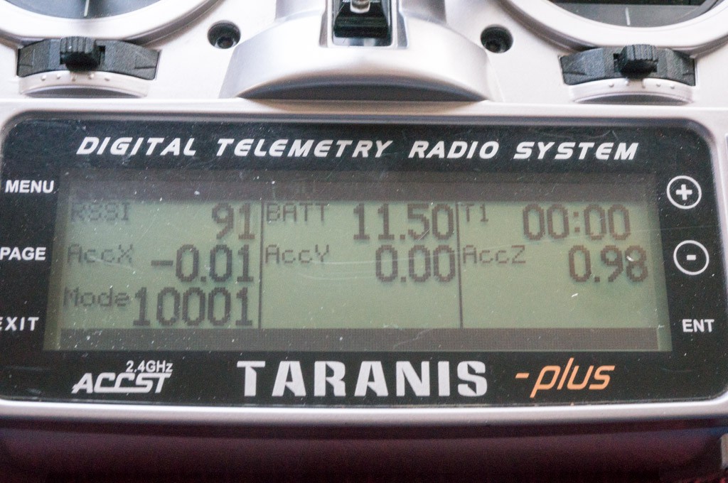
The next step was to configure the telemetry properly in the iNav configurator. I assigned the smart port telemetry to UART3. It took me a while to realize that I had to "set smart port_uart_unidir = ON" in the command line interface. After that, the Taranis was able to get the telemetry from the quad:
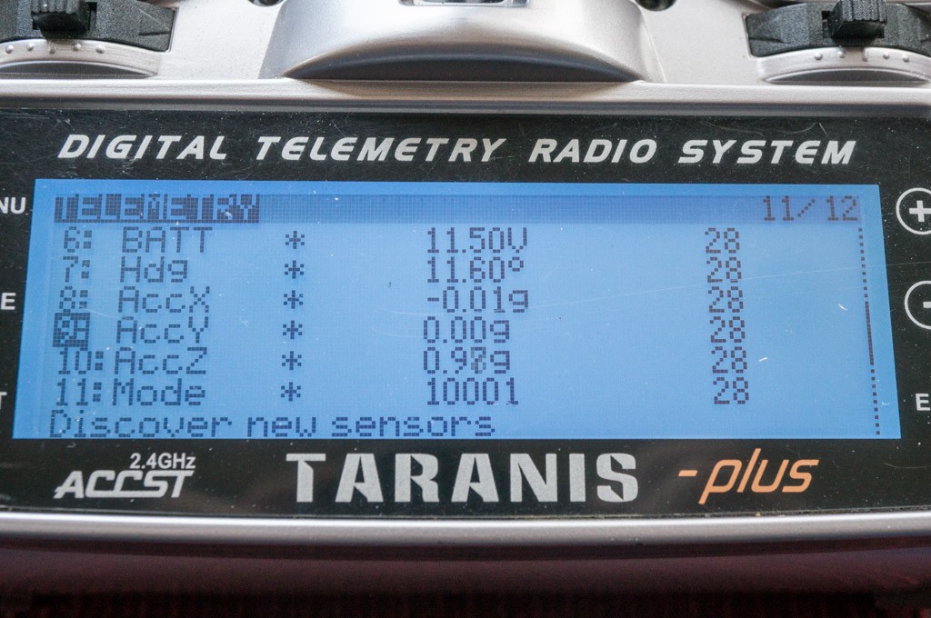
And I set up the sensor display temporarily:
At this point I'm pretty much done with this project. Things are working and I don't expect any problems with the smart port inverter going forward.
Discussions
Become a Hackaday.io Member
Create an account to leave a comment. Already have an account? Log In.