 Paul Andrews
You can get the board on OSHPark. The full KiCAD project and LTSpice model is in my Github repo. There is a full BOM with digikey part numbers in the files section of this project and in the Github repo.
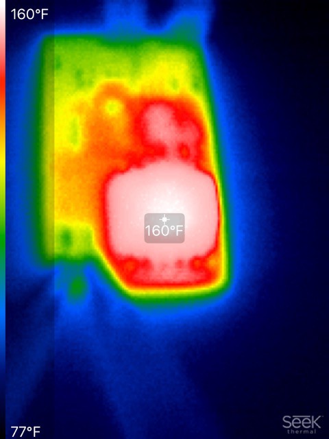
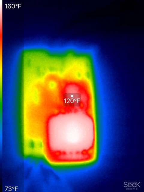
BTW, I tried reducing Rsense to 0.04Ω. The temperature of the transformer peaked at 160°F at an ambient of 70°. Still well below the absolute maximum of 257°F. I will produce a set of figures for this configuration too, as the supply can provide a lot more current with this lower value of Rsense
And the MOSFET:
A chart showing the maximum current for a given input and output voltage. I determined this from the readings that follow, by picking the maximum current I could measure before Vout started to be un-regulated. So another way of saying this is that it shows the maximum current for a regulated Vout.
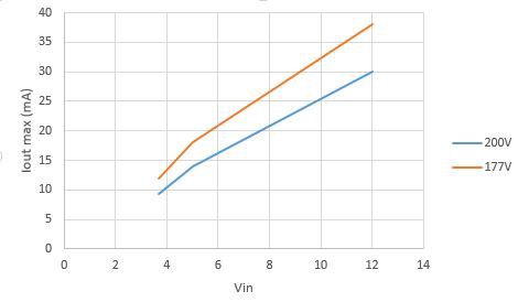
There might be thermal issues with running at these maximum currents. I couldn't really measure that because my load resistors need some serious heat sinks added first.
In the readings below it is useful to note that for a given load and Vout, the output current remains constant regardless of the input voltage (until the output voltage becomes unregulated)
Readings for a Vout limit of 200V:
| 12V in | |||||
| Rload | Vout | Iout (mA) | Vin | Iin (mA) | Eff |
| 19.31 | 199.8 | 10.40 | 11.96 | 237.90 | 0.73 |
| 14.64 | 199.7 | 13.70 | 11.96 | 298.20 | 0.77 |
| 10.00 | 199.4 | 20.06 | 11.95 | 414.00 | 0.81 |
| 6.86 | 199.1 | 29.23 | 11.93 | 595.00 | 0.82 |
| 4.65 | 188.4 | 40.00 | 11.88 | 765.00 | 0.83 |
| 5V in | |||||
| Rload | Vout | Iout (mA) | Vin | Iin (mA) | Eff |
| 19.31 | 199.3 | 10.38 | 4.80 | 600.00 | 0.72 |
| 14.64 | 199.2 | 13.68 | 4.72 | 717.00 | 0.81 |
| 10.00 | 177.2 | 17.82 | 4.63 | 865.00 | 0.79 |
| 3.7V in | |||||
| Rload | Vout | Iout (mA) | Vin | Iin (mA) | Eff |
| 19.31 | 199.0 | 9.30 | 3.67 | 865.00 | 0.58 |
| 14.64 | 181.0 | 12.30 | 3.65 | 890.00 | 0.69 |
| 10.00 | 146.0 | 14.00 | 3.49 | 906.00 | 0.65 |
Readings for a Vout limit of 177V:
| 12V in | |||||
| Rload | Vout | Iout (mA) | Vin | Iin (mA) | Eff |
| 19.31 | 177.8 | 9.26 | 11.97 | 195.50 | 0.70 |
| 14.64 | 177.7 | 12.20 | 11.96 | 243.10 | 0.75 |
| 10.00 | 177.6 | 17.86 | 11.96 | 345.50 | 0.77 |
| 6.86 | 177.3 | 26.00 | 11.94 | 471.00 | 0.82 |
| 4.65 | 177.0 | 38.23 | 11.91 | 678.00 | 0.84 |
| 5V in | |||||
| Rload | Vout | Iout (mA) | Vin | Iin (mA) | Eff |
| 19.31 | 177.2 | 9.22 | 4.84 | 502.00 | 0.67 |
| 14.64 | 177.2 | 12.14 | 4.77 | 620.00 | 0.73 |
| 10.00 | 177.0 | 17.76 | 4.63 | 870.00 | 0.78 |
| 6.86 | 152.0 | 22.40 | 4.60 | 930.00 | 0.80 |
| 3.7V in | |||||
| Rload | Vout | Iout (mA) | Vin | Iin (mA) | Eff |
| 19.31 | 177.4 | 9.24 | 3.82 | 610.00 | 0.70 |
| 14.64 | 177.0 | 12.17 | 3.64 | 900.00 | 0.66 |
| 10.00 | 144.2 | 15.00 | 3.49 | 914.00 | 0.68 |
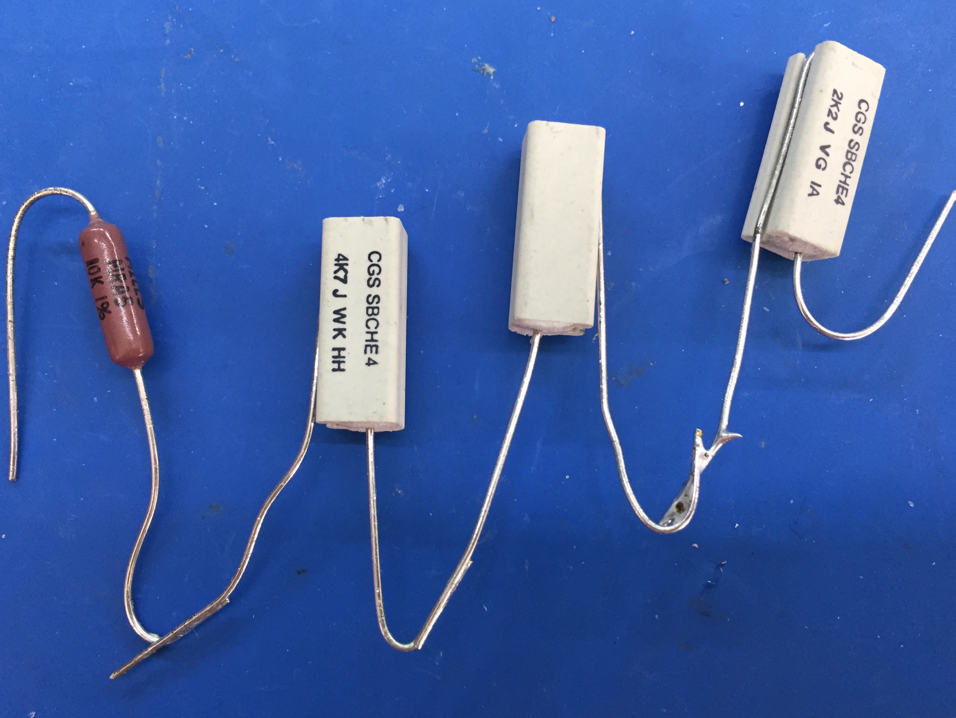
Here is my new test load rig. An extra resistor and a smaller form factor! I really need to get some heatsinks though. Or even better, an actual test load!
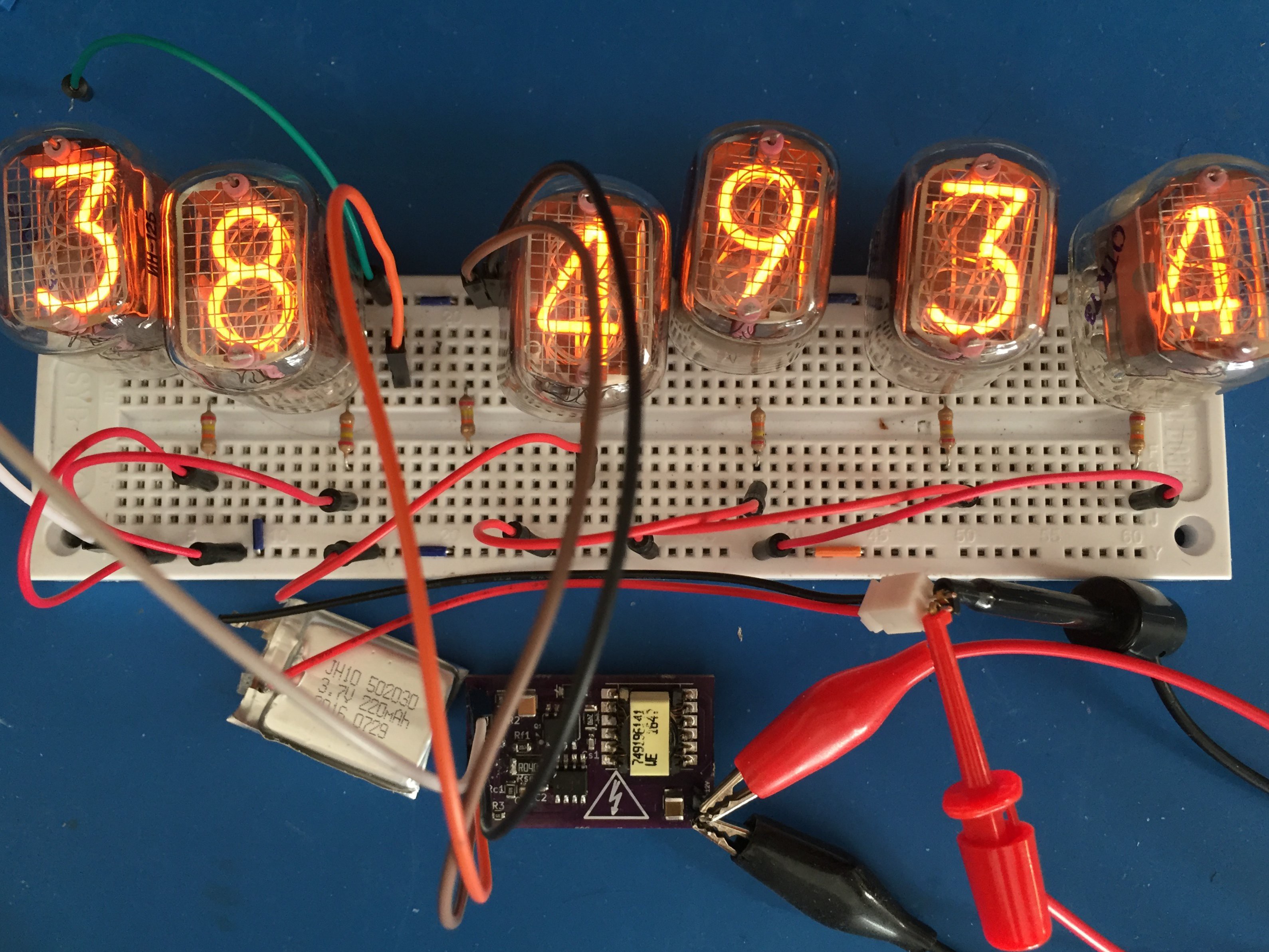
Here's a much more attractive test load being driven by a liitle LiPo battery:
Discussions
Become a Hackaday.io Member
Create an account to leave a comment. Already have an account? Log In.