 SHAOS
SHAOSOK, now we can take closer look at transparent keyboard circuitry and trace it by index finger :)
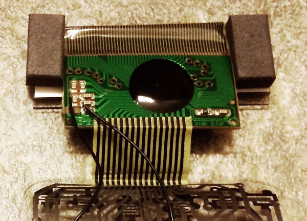
Green PCB connected to keyboard by 16-signal bus - we can enumerate signals from 1 (left) to 16 (right) and last one is not connected anywhere. After one night of insomnia I've got this matrix (what should be connected to what in order to simulate keypressing):
It could be directly used as a base for our instruction set - just rename 15 to 0 and we can take columns as higher nibble of opcode and rows as lower nibble of opcode, so ON would be 0x67; A=1 would be 0x48 (1), 0x6E (SHIFT), 0x4E (STO), 0x3E (A) and so on. Rest of the codes could be used for future branching, looping, comparison etc.
P.S. CASIO fx-82ms manual can be downloaded from here
Discussions
Become a Hackaday.io Member
Create an account to leave a comment. Already have an account? Log In.