Yes! It actually worked... but this whole thing needs improvement.
- The original PICBasic program had to toggle the pins in the timer interrupt, and spent all the time to do this kind of thing. I could not coax these PWM modules to toggle the TRIS instead - it has no High-Z or one alternating.
- By the time all that are toggling, very little time left to do the remaining calculation. All the frequencies and the timings are off, and there is no proper structure left in the program. Yeah, I would have added the third channel, but sooner or later it sounds like a warped broken toy.
- The original article suggested cranking up to 40MHz for all that, but again, from the last two points, it only leaves too little room for other improvement.
- The code from the previous log was only two channels - adding one more of it resulted in a terrible warped and slowed sound. Not even good, and that was why I tore it down afterwards.
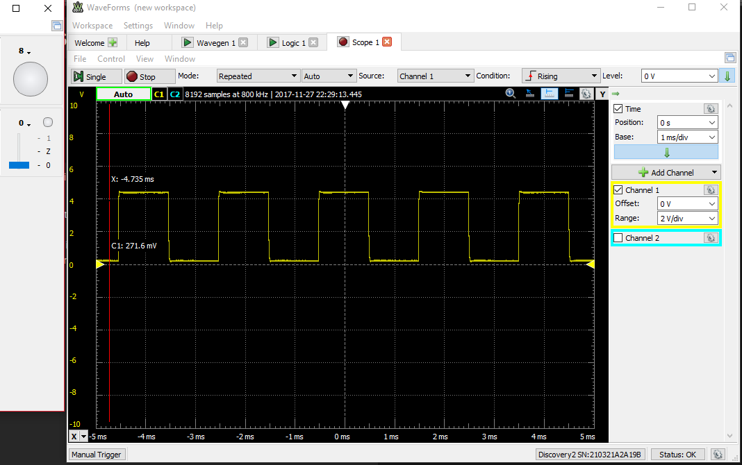
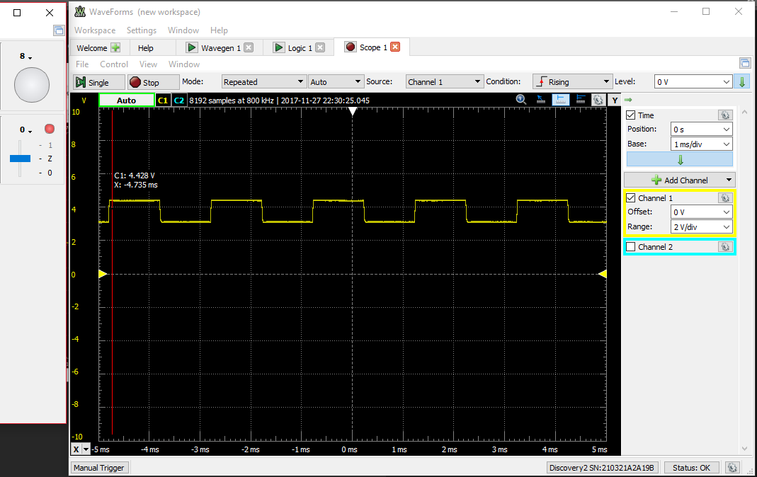
Here are the results, using the first schematic on the first log, and toggling the TRIS instead of the PORT bit:

The switch is at 0.

The switch at High-Z.
What you did not see was the amplitude of the square wave decreases slowly, but it is moving upwards instead of downwards. I suspect the sound has diminished, but not a lot. There was some modifications earlier which I needed to manually recover...
Discussions
Become a Hackaday.io Member
Create an account to leave a comment. Already have an account? Log In.