Portrait Plotter
An interactive installation that takes your photo and paints it on paper.
An interactive installation that takes your photo and paints it on paper.
To make the experience fit your profile, pick a username and tell us what interests you.
We found and based on your interests.
During the last three weeks, I went to three exhibitions with the Portrait Plotter. That was fun, but I’m a bit exhausted now. It also got me some exercise in hauling the whole thing around – it now takes me 3 hours to set up and 2 hours to dismantle.
Maker Faire Zürich was as awesome as every time. I just love the jam-packed creative atmosphere at that event. As usual when exhibiting alone, I couldn’t visit all the talks and exhibits I would have liked to, but seeing visitors playing delightedly with the Portrait Plotter, marble run, and LED panel made up for that. An interview where I talk about my work was published in advance of the event.
During the Maker Faire, I was approached and invited by the organizer of Flick the World, a smaller and more improvised festival in Zürich aiming to connect different maker/tinkerer/artist communities, especially also from the field of music and video. That was fun too, and this time I got ample opportunity to interact with other participants and their works. With just five other exhibits, the Portrait Plotter got a prominent place and was kept remarkably busy. The organizer suggested asking for donations rather than a fixed price for a plot, which seems to have worked very well. Total revenue over the two days was a littler lower than at the Maker Faire, but I did get the impression that it increased visitor engagement, reduced a barrier, which is a trade I am happy to make. I therefore plan to stick to that “pay what you want” model for now.
Last Friday, the Startup Night Winterthur took place at the startup incubator that also hosts FabLab Winti, and the FabLab was also present with a booth among the startups promoting their products and services. As an active member of the FabLab, I was invited to present the Portrait Plotter there as an example of what can be made in a FabLab. That turned out a somewhat special experience, as the audience of such a fair clearly expects companies trying to sell their products, not art installations created by hobbyists. Many visitors showed no interest at all, with others it took some explaining to make clear what the point of this installation was. But I still sold a few plots, had a few nice conversations, and reached some people outside of my usual interest group that I wouldn’t otherwise have reached, so I am not dissatisfied.
Here is the new control panel that addresses some of the shortcomings mentioned previously:
It is longer and mounted higher up to make it better reachable, it includes a connector for a foot switch to complement the trigger button, and it features some more knobs to play with: A potentiometer to adjust the red/green choice to the ambient lighting (or just modify it artificially), and two push buttons that exchange the colors in the final image, to give a preview of what it will look like when plotted with different pens. These also light up in the chosen colors. To achieve this, I ripped out their original white LEDs and instead illuminate them from the side with a two-LED piece of NeoPixel strip.
The additional space also allows mounting the Arduino board and the 5V power supply beneath the panel, which reduces the clutter inside the pyramid.
It is all wired up and the Arduino software written, now I just need to make use of it in the image processing application.
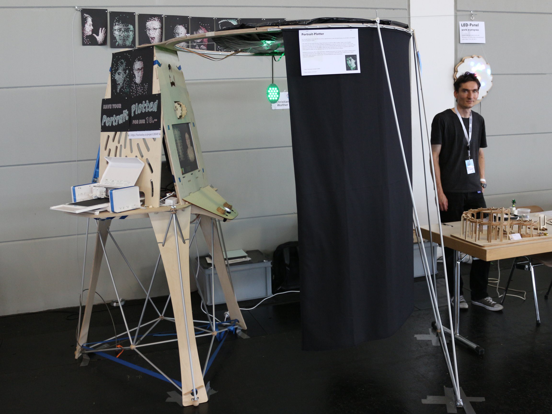
Maker Faire Bodensee was fun and interesting, but not as overwhelmingly awesome as I had found Maker Faire Zürich in the past two years. Why? I can’t really say myself. While I like having some room to breathe, maybe spreading out over the large exhibition hall somehow diluted the maker spirit, compared to the crammed space in Zürich? What certainly played a role is that there were fewer visitors than I expected. Especially on Sunday, I sometimes spent 15 minutes or so alone at my booth, which was a bit boring.
This also reflected in the revenue from the portrait plotter – 8 portraits sold during the two days, little more than I had sold in three hours at the holiday market. I was hoping that the portrait plotter would pay for the booth rent, but I missed that goal by more than a factor of two. One visitor suggested that I might have sold more at a price of 5 Euros instead of 10. Could be that I had the Swiss price level in mind when I set that price and Germans are more sensitive there, but then the price is arbitrary anyway (as the marginal cost of one portrait is negligible compared to the cost of building the machine) and it does not feel too high to me for a piece of art.
The portrait plotter also appeared to be less of an attraction than I had expected, many people seemed to walk by without taking notice, in spite of its size. Maybe they did not understand what it did, or maybe it was not clear enough that they could try it on their own, without asking, for free? Still, feedback from those who did take notice was very positive, and I had some nice conversations with visitors and other makers. On top of that, I received a Maker of Merit award from the organizers, which was a nice surprise.
Technical insights from this round:In summary, I won’t run out of things to improve until Maker Faire Zürich in September, for which I just signed up!
This week I made potentiometer knobs for the control panel, bent the curtain rails and mounted them to the cabin ring, and sewed the black curtain. Now, just in time, with less than a week to go until the Maker Faire, I am finally at a stage where all the parts can be assembled for the first time. And everything seems to work! :D
Minor issues to be addressed in a later iteration:
With all the sanding done, here is the pyramid, assembled for the first time.
I continue to be impressed with Onshape. Its “edit in context” feature makes it very easy to design such tab-and-slot constructions with arbitrarily arranged parts. Here’s the document again.
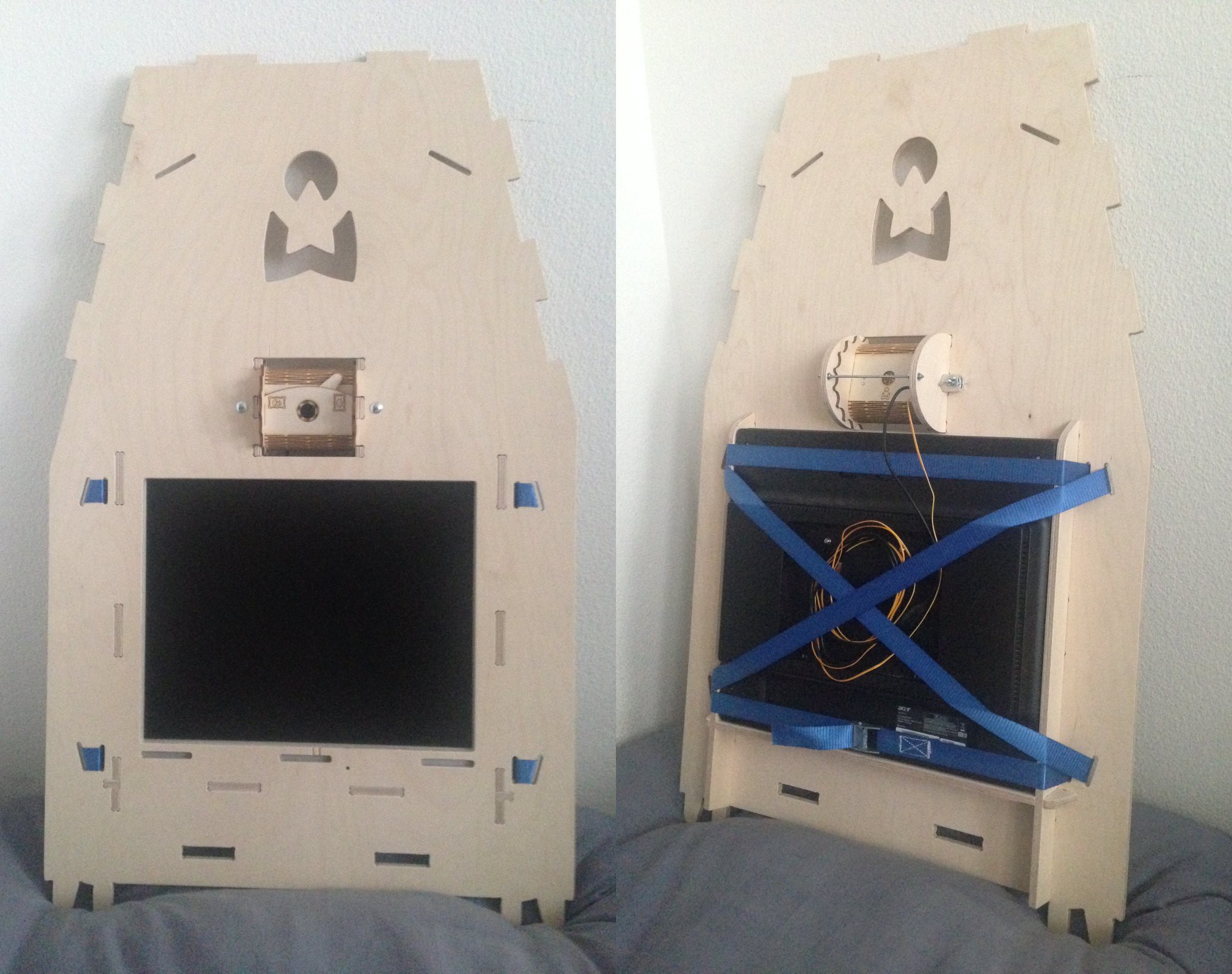
One of three sides of the upper pyramid.
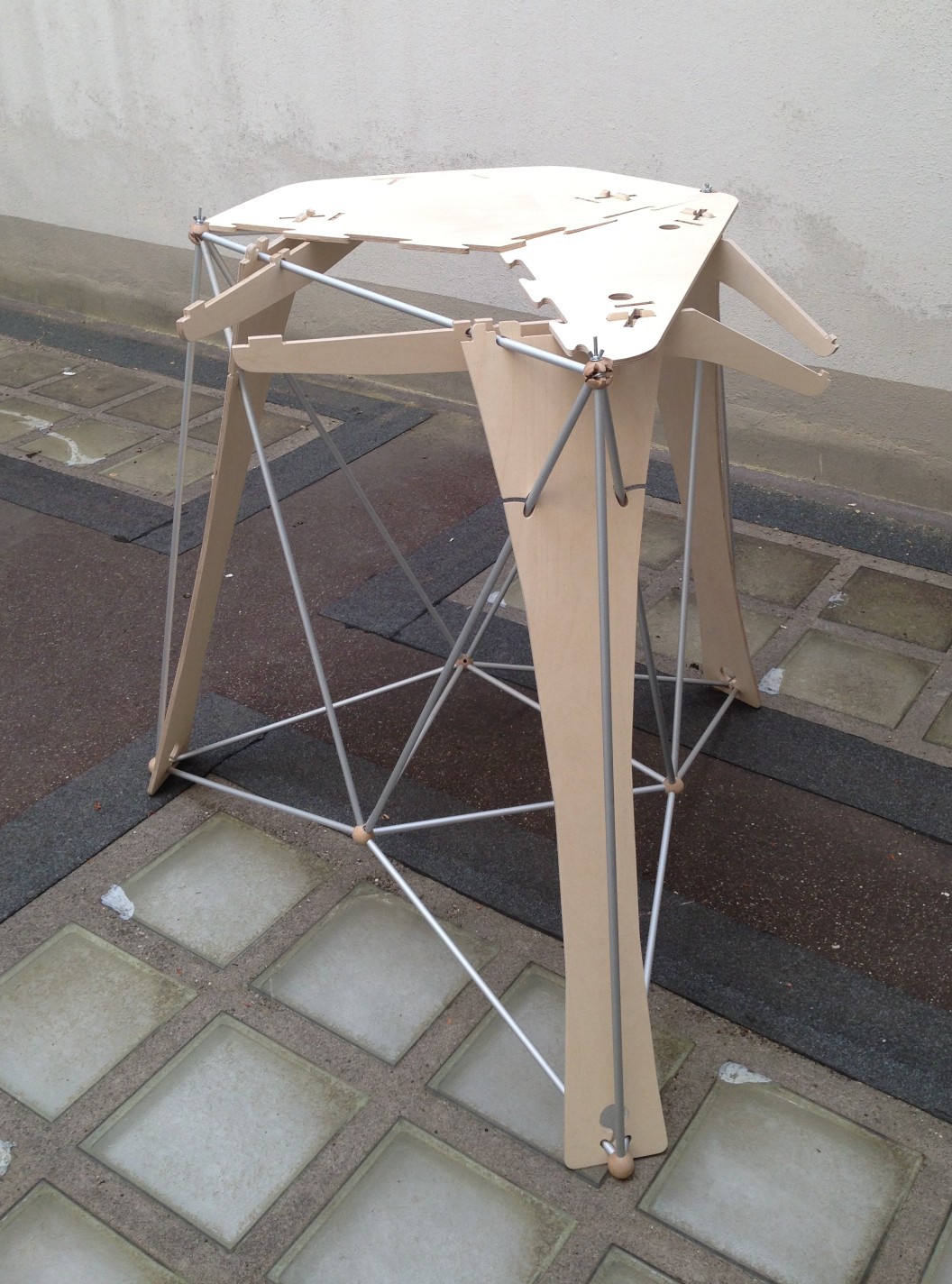
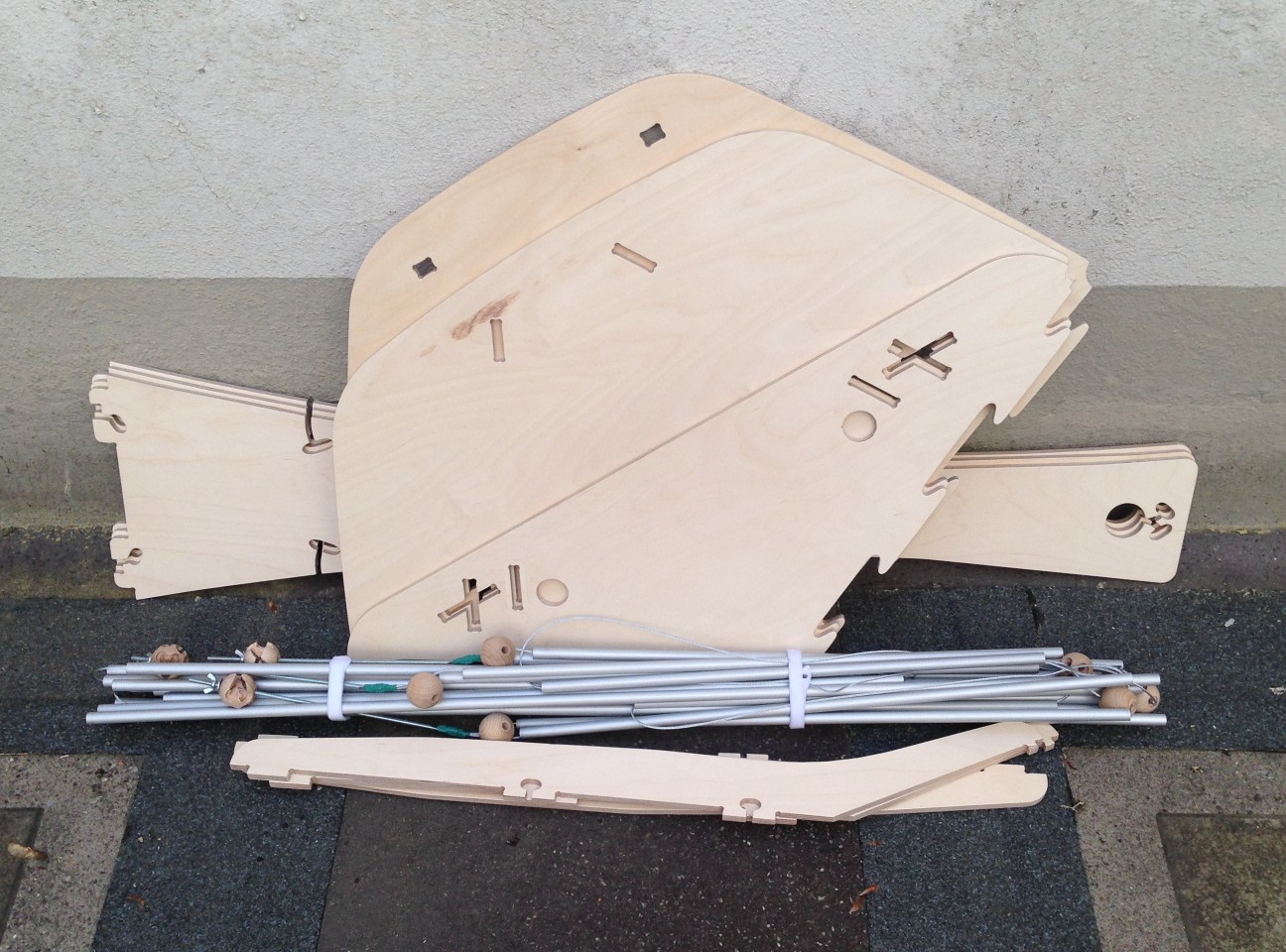
The “space frame” idea for the tower part turned out feasible, so I went ahead with that one. The space frame construction, made of the same 12 mm aluminum tubes, 2 mm steel cable, and 35 mm hardwood balls as the stand for the cabin part, is rock solid, even by itself. I didn’t dare sitting on it, but I piled about 16 kg of stuff on it and it didn’t budge. I suspect the weakest points are the wooden balls, and I half expect that at some point one of them will burst with a bang. This should not cause too much damage however, as the tubes can’t move very far without them, still being held together by the cable – except in one case with the joints at the bottom center, where there is one piece of cable that is not wrapped around the other ones because there wasn’t space for it inside the ball, so if the ball breaks along that plane, the joint will fall apart into one piece with two tubes and one with four. This can be mitigated by reducing the tension in that direction using an additional belt around the legs.
The wooden legs, which are maybe a bit overdimensioned, as two of them alone turn out to easily hold my weight, are designed to both bear the majority of the load and hold the tubes in place in the event that a ball breaks. All the wooden parts are CNC-routed from 9 mm birch plywood. Their sizes push the limits of the CNC router at FabLab Zürich, which was also the reason why the table is split into three parts (apart from allowing it to be assembled in two mirrored arrangements). Making efficient use of the material is hard when the parts are so large that only one of them will fit into the router at a time, so I now have lots of oddly shaped plywood residuals sitting in my home. I will think of something to build out of them…
On top of the table, a truncated pyramid of three more plywood parts will hold all the components. I routed the last one of them today, but still have lots of rough edges to sand on all of them.
This week I signed up as an exhibitor for Maker Faire Bodensee, with the portrait plotter as my main exhibit. There is not a lot of time remaining until June 2nd/3rd, but I hope to get a somewhat more permanent mechanical structure done by then. The goal is to build something that can stand on its own, but is lightweight and easily disassembled into pieces of about 1 meter in length for transport. Here is how the photo cabin part that will hold the black background curtain and the LED lights is coming along:
The stand made of aluminum pipes tightened together with a thin wire rope on the inside turned out a little wobblier that I had hoped for (mainly due to the elasticity of the wooden ring), but it still bears more weight than it needs to, so I am satisfied for now.
For the tower part that will support the other side of the ring and house the monitor, camera, control panel, computer, and plotter, I am still exploring several possibilities.
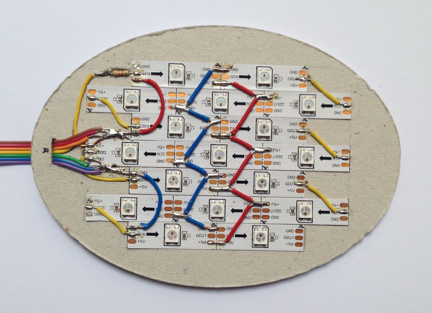
This is one of the two LED lights as it was made in December: NeoPixel strips (left over from my LED panel project) mounted on gray cardboard. Power and signal is delivered over a ribbon cable where 3 wires each are connected in parallel for the power lines, empirically determined for an acceptable voltage drop at maximum current. Some of the red and blue power wires between the strips are redundant in order to get a more even voltage distribution under load, however I did not measure whether that was actually needed.
There are conflicting opinions on whether it is safe to power an Arduino Uno through its 5V pin while it is also connected to a computer by USB, so what I did was instead power it by USB from a powered USB hub, which in turn is powered from the 5V power adapter that also powers the LED lights. This way, the hub takes care of not feeding power back into the computer.
Now, for the final setup, I enclosed the LED lights in a sandwich of more cardboard and paper parts with cutouts for the internal components (cut on the Curio), an MDF back plate, and an acrylic front plate (lasercut). With the neck of the acrylic part, the lights are hung from a circular curtain rail that allows them to be moved 360° around the subject.
I still owe you some posts about the December hardware, but in the meantime here’s what I made today:
A camera housing with an adjustable vertical angle and a lever that rotates the camera by 90° to switch between portrait and landscape orientation. It contains a switch that detects the orientation and will tell it to the software via the Arduino. All held together by a single bolt, no glue.
The 4 mm (actually, 3.75 mm) poplar plywood turns out to be a bit too brittle for the stressed moving parts, one of them broke already – maybe I’ll try redoing them in MDF. But for now it’s working.
Onshape’s sheet metal tools turn out useful for the bent plywood parts – you design them in 3D and it automatically lays them flat. Only the slit pattern for the bends was added by hand in Illustrator. (Here’s the document if you want to take a peek.)
Create an account to leave a comment. Already have an account? Log In.
Thanks for your comments! I just saw them now – I’m supposed to get email notifications for these, but somehow that didn’t happen.
1. Yeah, for a software project I did spend an extraordinary amount of time designing furniture! I’m quite happy with how it turned out, constraints like the router size and transportability requirements led to some creative solutions.
2. That’s a good idea, I’ll try that next time I play with the image processing.
3. I don’t at this time, but then the plotter is a popular commercial one (Silhouette Curio), so you can probably find some elsewhere. A quick YouTube search for example turns up this one: https://www.youtube.com/watch?v=_hkZEec5GD0
Become a member to follow this project and never miss any updates
1. Your table design is amazing (and this isn't even a furniture project)!
2. I think you might get better results on certain images (specifically those where there are regions of different average luminance that you still want to include in the output, like the two-faces example in your first log entry) by applying a high-pass filter before the gamma step, but after background removal (or identify the background before HPF and then apply that mask later). That'll bring those regions to the same overall luminance, while preserving detail.
3. Do you have a video of your plotter working? I love pen plotter videos.