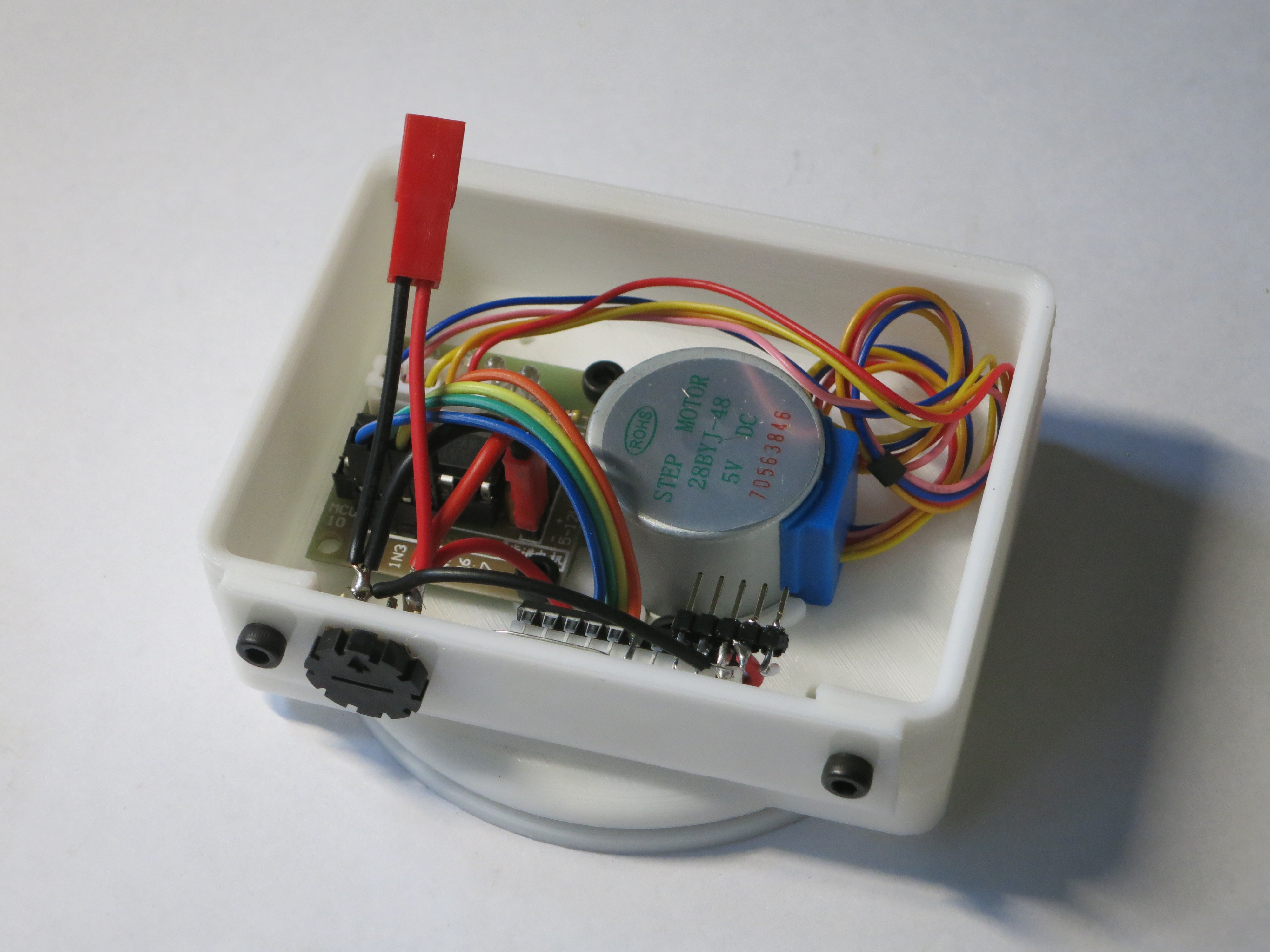
Hackaday Superconference 2017 kicks off tomorrow! Clock is ticking for me to complete my preparation work. My 3D printer is hard at work churning out iterations of my motorized base for panning photo/video. I had originally intended to drive the whole works with my three-cell lithium lion battery pack built from cells salvaged from a Dell laptop battery pack. The battery power will go straight to the power coils of the stepper motor and a voltage step-down converter will reduce the voltage for the ULN2003 chip driving the steppers and my PIC16F18345 running a program to run the works.
The stepper motor is designed for nominal operating voltage of 5 volts, but the actual limit on stepper motor operation is the amperage running through its coils. I thought I could drive the coils with pulse-width modulation and keep the power under control. The batteries power is about 12 volts, so a 40% duty cycle should be a good approximation.
But real life got in the way of my plan with these unipolar stepper motors. As the coils are energized and de-energized in the PWM cycle, magnetic field and electrical current were getting sent elsewhere in the motor in ways I didn’t understand. Causing the motor to behave erratically instead of just turning at a lower power.
If there wasn’t a looming deadline, I would hit the web searches to learn and understand what’s going on so I could fix the problem correctly. But I do have a deadline and needed a quick fix. “Just” running the motor at full power isn’t a solution. The motor could run at ~12V but it gets very hot. If I was only using the motor to turn infrequently, this might be OK. But a camera pan base is constantly turning slowly.
In order to keep the coils energized with a lower voltage, I changed the power supply to a 4-pack of NiMH AA batteries. Their nominal voltage of 4.8 is close enough for my purposes. It is smaller and lighter than the Li-Ion pack and also eliminates the need for the voltage regulator. The trade-off is a drop in power capacity… which may or may not be important. We don’t know yet. I guess I should pack a NiMH battery charger.
Once the stepper motor power was sorted out, I added a potentiometer to give manual control of rotation direction and speed. Once I finish 3D printing a case around this, I will have a minimal implementation of the mechanical base.

(Originally posted to NewScrewdriver.com)
 Roger
Roger
Discussions
Become a Hackaday.io Member
Create an account to leave a comment. Already have an account? Log In.