After the mechanical bits were assembled yesterday, I worked on the simple PIC program I’d need to drive it. This involved refining the exploratory code into something that resembles an usable device. Things like no longer running on a fixed program but read the potentiometer I wired into the circuit to dictate motor control. Fortunately most of the hard work is done by MPLAB X boilerplate code, I only had to weak a few things here and there to end up with the functionality I want.
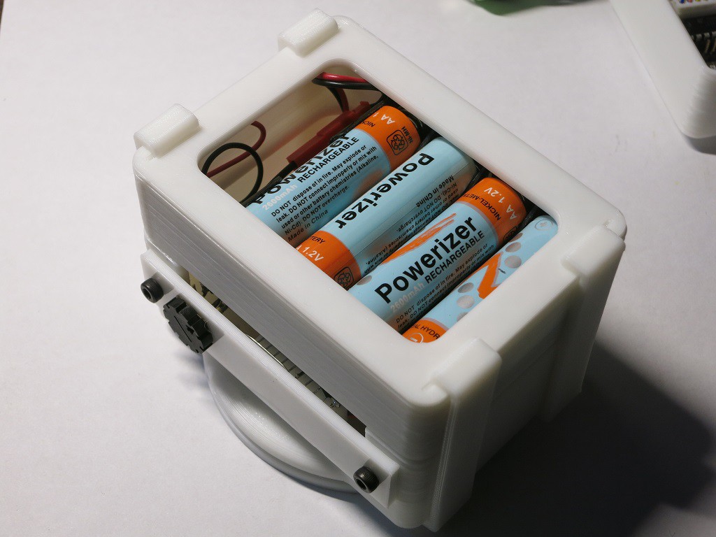
I also 3D-printed the remaining layers of the enclosure – the battery tray, a minimalist lid, and the little flexible clips that hold them all together. The layers are an extremely tight fit because the wiring plugs were longer than I expected. Right now they’re pressed against the bottom of the battery tray which is not good for connector health. I’ll increase the height for the next iteration to give everything more headroom.

The good news is that everything runs. The bad news is that it doesn’t run very well. I dug a digital camera with a built-in time-lapse mode, set it on top of the base, and shot a few clips. The jittery motion of this cheap DIY pan base is very clearly visible in the resulting video. There’s a reason professional photography pan heads cost a lot of money – they have much smoother bearings and better motors for fine control.
Since the conference kicks off tomorrow, I’m going keep forging ahead with what I have. No time to find better motors or bearings. There are a few issues that I might be able to fix in the PIC software, but the sticky jittery motion from the motor and bearing isn’t something I expect to be able to fix in code.
Well, I can hope the jittery motion is not visible in the default 128×96 resolution of the camera!
(Originally posted to NewScrewdriver.com)
 Roger
Roger
Discussions
Become a Hackaday.io Member
Create an account to leave a comment. Already have an account? Log In.