 SUF
SUFAs the other PCBs are arrived for the supply, I continued the build.
Finished the separated isolated supplies for the panel meters (these are nothing else just a simple dual 7809 based linear supplies):

Also added the power distributor and some wiring for the backpanel:

Connected the panel meters and, milled parts of the front panel (manually as my CNC mill is still broken)
How the whole thing looks like today:
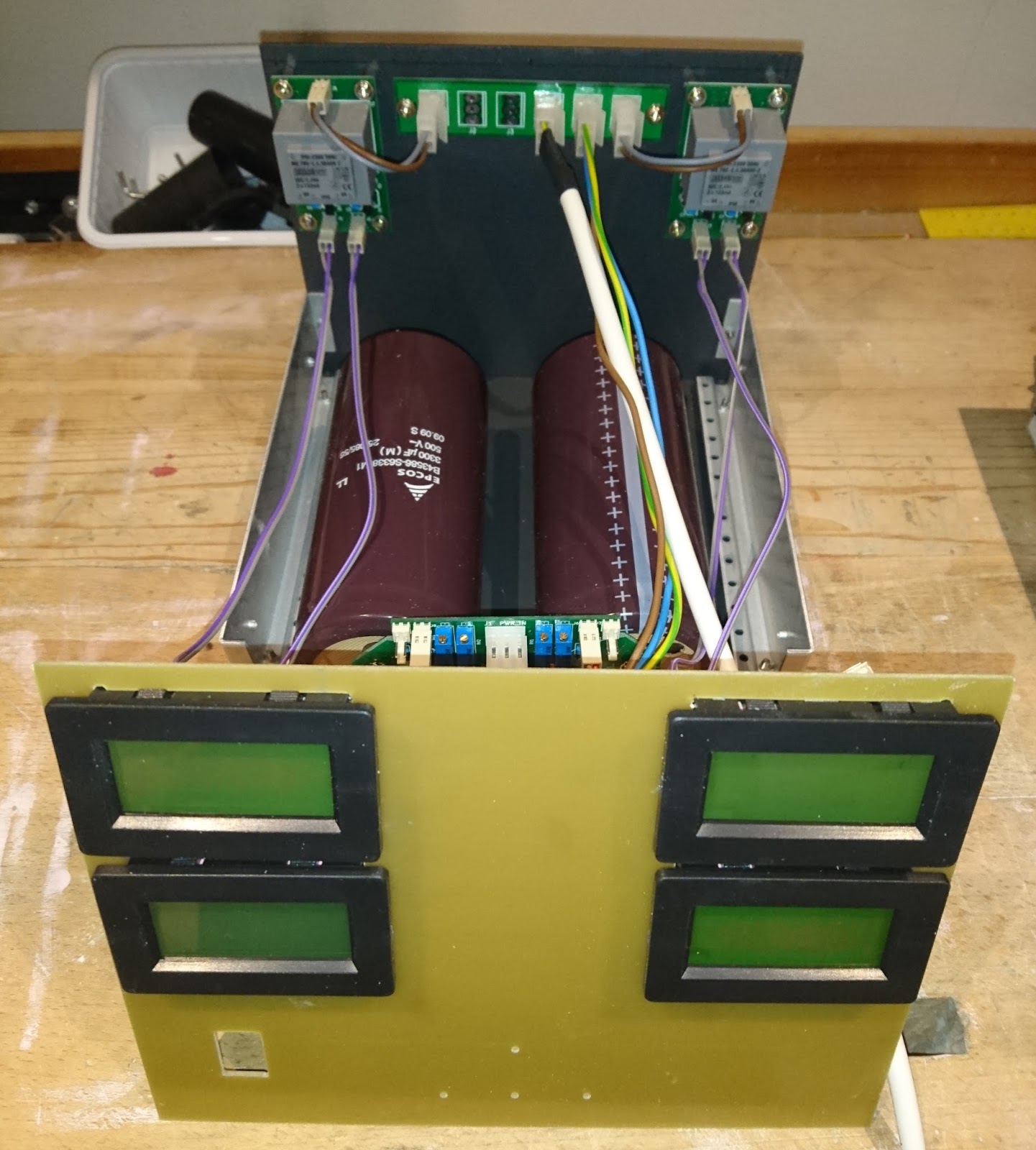
And its working, partially:

As you see the decimal dot is on the bad place (it is more likely 330V than 33V)
In addition I took a picture of the board on thermal camera. You can clearly see that the two capacitor draining resistors getting warm:

So I can tell, it is progressing, but quite few things still ahead of me:
- Mill a hole for the mains socket and the circuit breaker to the backpanel
- Mill the holes for the banana jacks to the front panel
- Finish the wiring
- Set the correct decimal dots
- build a dummy load to be able to test the current measurement
- Calibrate
- Paint the front panel
- Build the phase switching electronics (not mandatory, maybe after finish)
- Create the console for the caps
Discussions
Become a Hackaday.io Member
Create an account to leave a comment. Already have an account? Log In.