Things You Need
Hardware Components:
- DFRduino UNO R3
- DFRobot I/O Expansion Shield
- DF05BB Tilt/Pan Kit(5Kg)
- DFRobot Photocell x 4
- Resistor 10kOhm x 4
- DFRobot Solar Panel
Software:
- Arduino IDE
Tools:
- Solder Iron
In modern solar tracking systems, the solar panels are fixed on a structure that moves according to the position of the sun.
Let us design a solar tracker using two servo motors, a light sensor consisting of four mini photocells and Arduino UNO board.
Assembly of the Pan Tilt
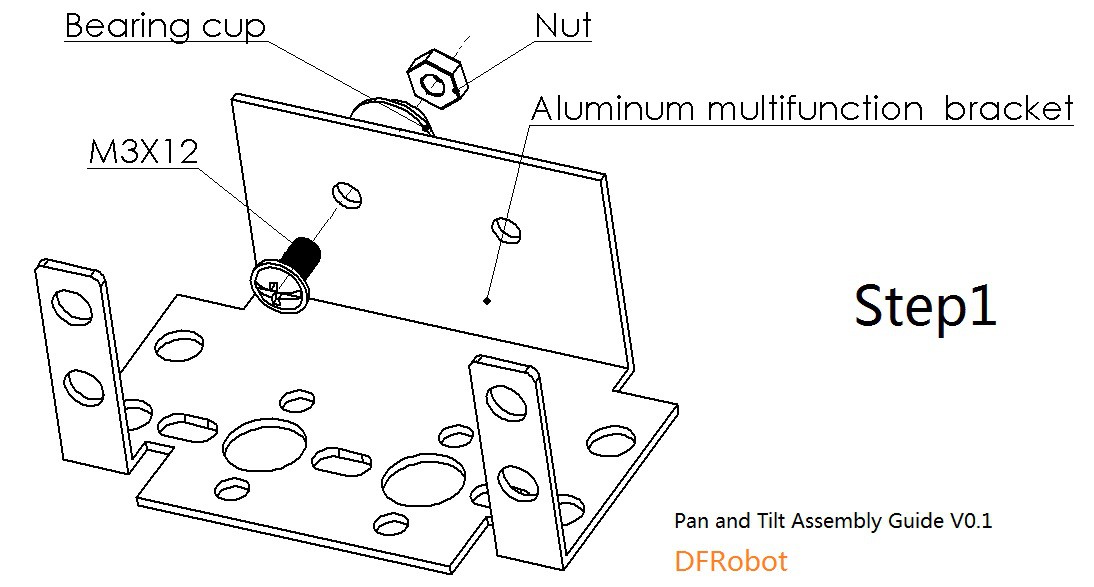

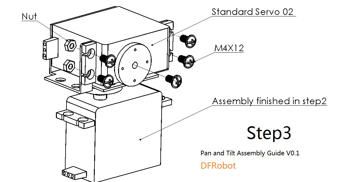
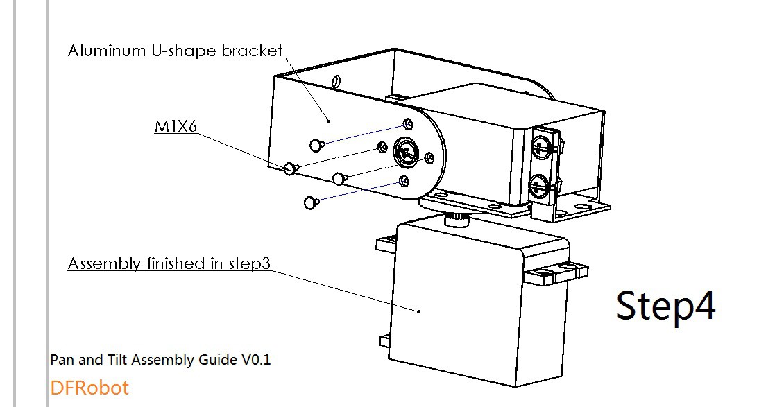
Follow the steps in the images above and assemble the parts.
Remember: Use rubber spacers when using the M1x6.
Connections
Stack the I/O Expansion Shield on the Arduino.
- Connect lower servo with D9 in shield.
- Connect upper servo with D10 in shield.
- Take +5V and GND to power rails in breadboard.
- Connect +5V in breadboard to each photocell.
- Connect upper left photocell to A0.
- Connect upper right photocell to A1.
- Connect lower right photocell to A2.
- Connect lower left photocell to A3.
- Connect GND terminal of each photocell to GND with 10k Ohm resistor in series.
Fixing and Testing
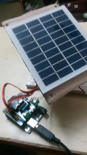
- Fix the Solar Panel on a cardboard and paste it on the face of upper servo.
- Take out all the wires and give them a play so as to move about 180 degrees.
- Put the system on a stable platform.
- Upload the code and test it with a bright LED or a bulb.
Schematics
Image source : Electronics Hub![]()
CODE
#include<Servo.h>

Servo servohori;
int servoh = 0;
int servohlimithigh = 180;
int servohlimitlow = 0;

Servo servoverti;
int servov = 0;
int servovlimithigh = 180;
int servovlimitlow = 0;

//Assigning LDRs variables
int ldrtopl = 0;
int ldrtopr = 1;
int ldrbotr = 2;
int ldrbotl = 3;

void setup() {
  servohori.attach(10);
  servohori.write(0);
  servoverti.attach(9);
  servoverti.write(0);
}

void loop() {
  /* code */
  servoh = servohori.read();
  servov = servoverti.read();

  //capturing analog values of each LDR
int topl = analogRead(ldrtopl);
int topr = analogRead(ldrtopr);
int botl = analogRead(ldrbotl);
int botr = analogRead(ldrbotr);
// calculating average
int avgtop = (topl + topr) / 2; //average of top LDRs
int avgbot = (botl + botr) / 2; //average of bottom LDRs
int avgleft = (topl + botl) / 2; //average of left LDRs
int avgright = (topr + botr) / 2; //average of right LDRs

if (avgtop < avgbot)
{
  servoverti.write(servov +1);
  if (servov > servovLimitHigh)
   {
    servov = servovLimitHigh;
   }
  delay(10);
}
else if (avgbot < avgtop)
{
  servoverti.write(servov -1);
  if (servov < servovLimitLow)
{
  servov = servovLimitLow;
}
  delay(10);
}
else
{
  servoverti.write(servov);
}

if (avgleft > avgright)
{
  servohori.write(servoh +1);
  if (servoh > servohLimitHigh)
  {
  servoh = servohLimitHigh;
  }
  delay(10);
}
else if (avgright > avgleft)
{
  servohori.write(servoh -1);
  if (servoh < servohLimitLow)
   {
   servoh = servohLimitLow;
   }
  delay(10);
}
else
{
  servohori.write(servoh);
}
delay(50)
}

 Hari Wiguna
 spark buzzer
Have you referenced any case studies on trackers vs. stationary systems such as with https://www.allearthrenewables.com/blog/dealers/pv-tracker-vs-pv-fixed-mount-system ? I wonder if there are comparable metrics you could try to construct for your design relative to a stationary unit (?).