 SimpleTronic
Quick Tour Video
Link to PCBoard , HEX code & assembly code
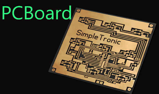
single sided PCBoard
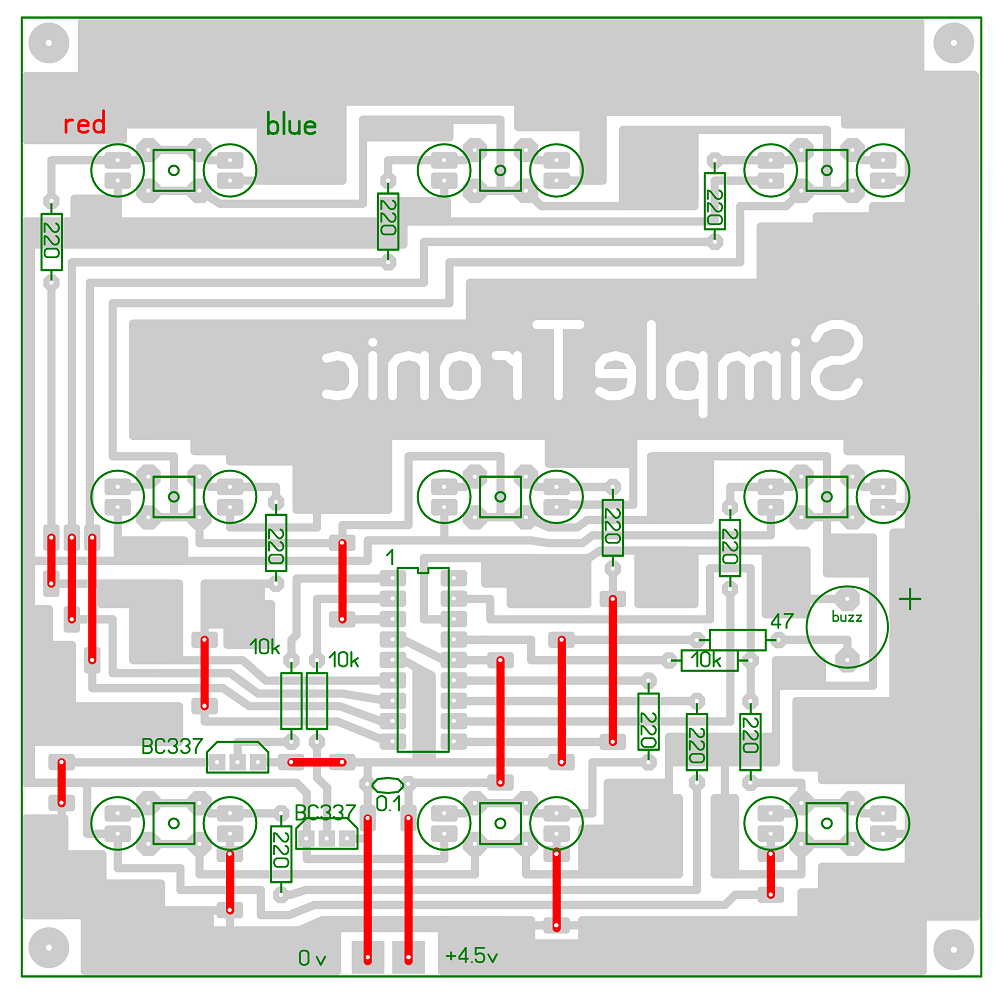
Components layout guide
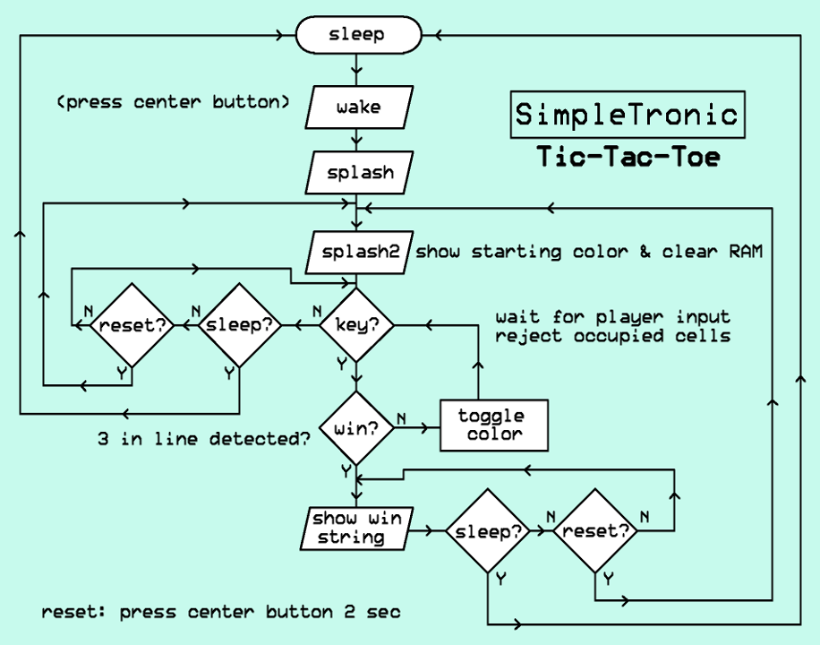
Basic Flowchart
Device enters SLEEP after 20 seconds of inactivity. Pressing the center button wakes the processor and displays a short splash sequence pattern with all LEDs. Finally, 3 blinks indicate the starting color (player). Device can be reset at any time by pressing the center button for 2 seconds. When 3-in-row (winner) is detected, the 3 LEDs will blink continuously while all the rest will turn off. Pressing the center button resets the game and toggles the starting color.
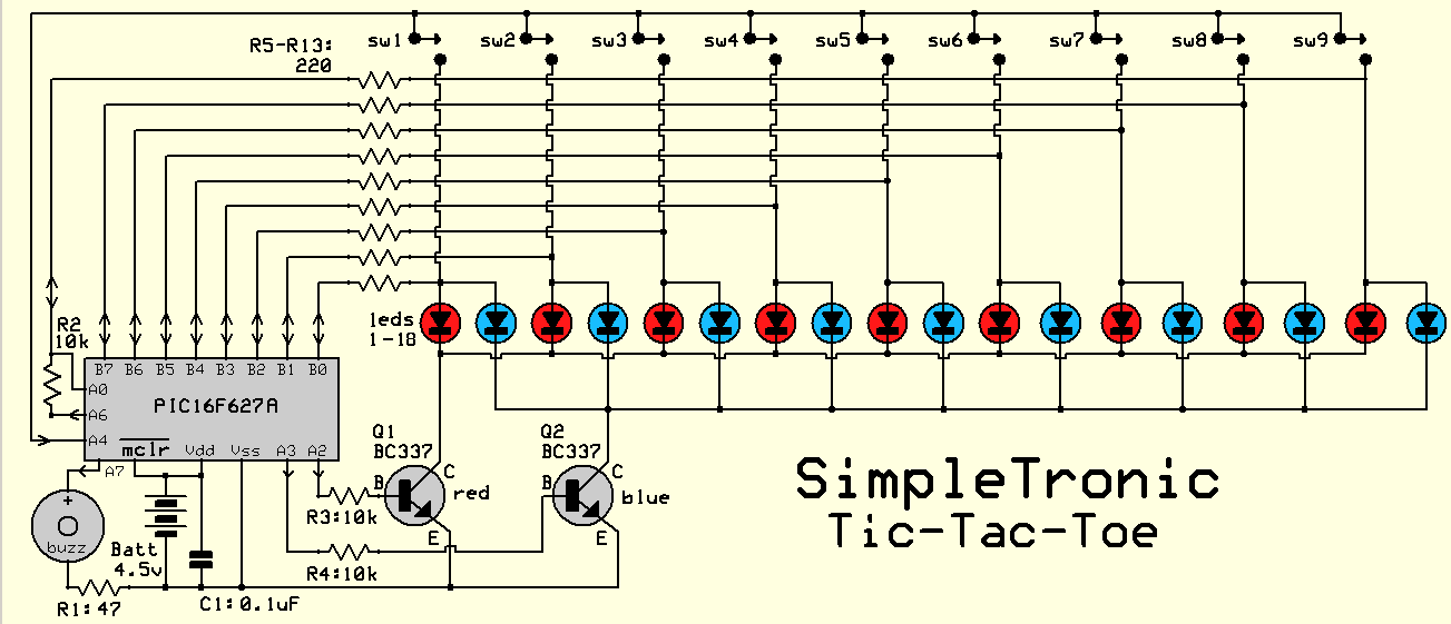
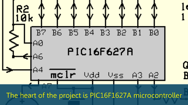
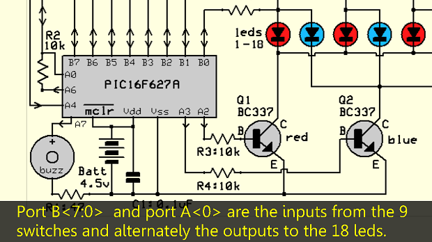
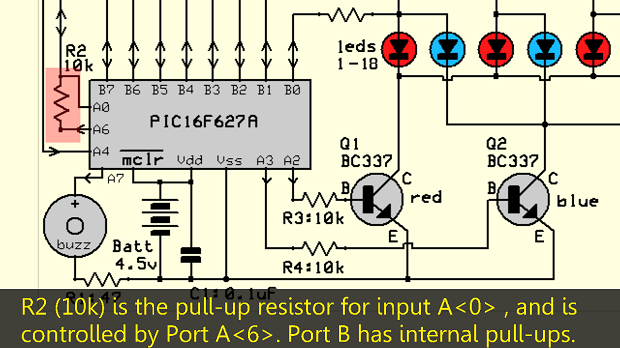
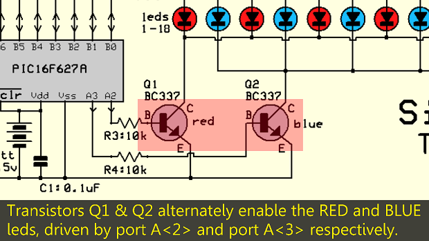
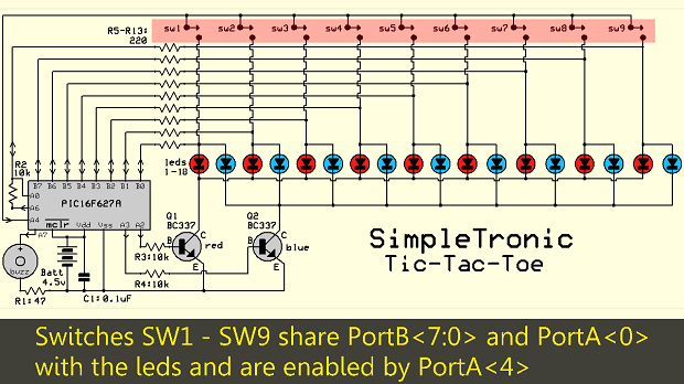
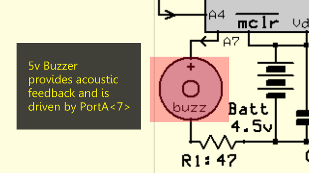
CIRCUIT DIAGRAM:
CIRCUIT OPERATION DETAILS:
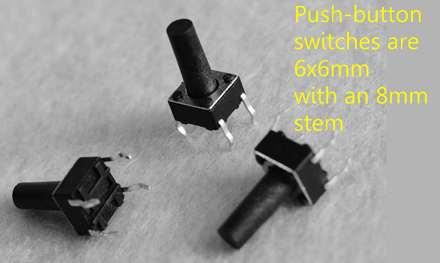
COMPONENTS LIST:
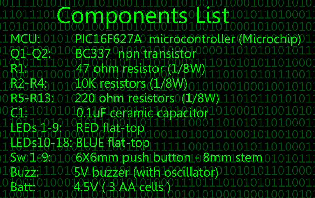
DETAILS:

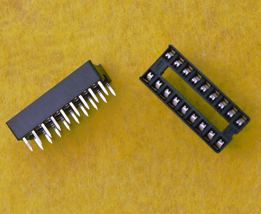
18-pin DIL socket for PIC16F627A
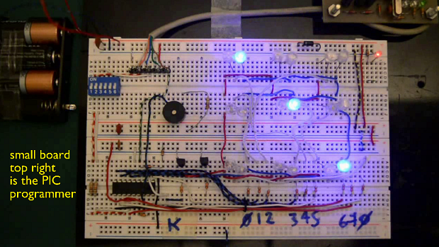
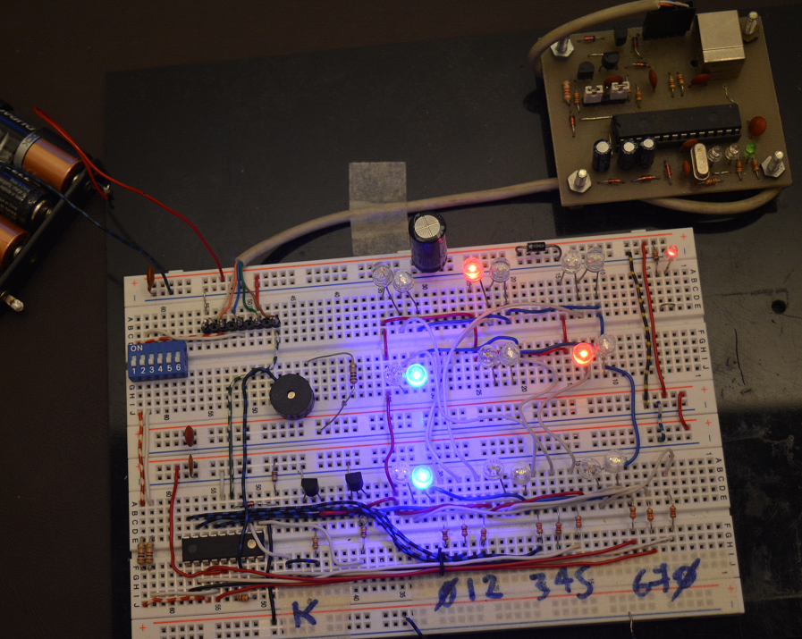
BREADBOARD TIME
I used a piece of wire to emulate the 9 switches.
Small board top right is the PIC programmer. If you don´t have a dedicated PIC programmer and are an ARDUINO user, you can use it to program the PIC. (serch the web).