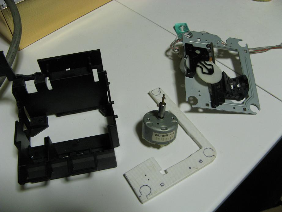
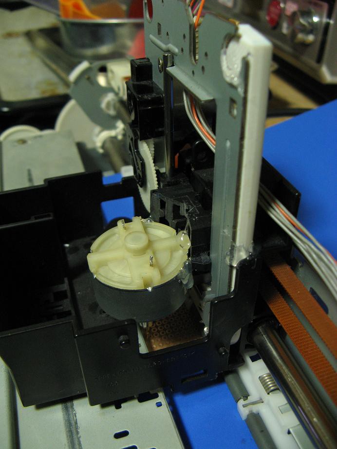
Before you glance at the pictures and laugh at my poor engineering skills, read the log.
I trimmed several bits of plastic off the print head carriage , made an adapter out of a piece of plastic cutting board from the garbage, and tacked everything together with a little hot glue to test the fit. It all went together well, and you can see that the rollers nicely accept a 1.6mm protoboard, even with the blue plastic backing sheet.


But then I took a look at what I had built and started pushing things around. I started having doubts. There is a little too much slop and I don't know how well the z-axis motor and gear set will perform. It works perfectly for moving a pen across some paper, but there will be significant forces on the bit.
It's time to rethink this part. I am currently pondering some other designs. A bolt attached to a stepper and a long nut attached to the cutting motor would give me the strength and z-axis precision I need. How about a piece of PVC slightly sanded and lubed sliding inside a PVC coupler, with the motor glued in the moving piece and the other held rigid. That would take care of lateral forces. I can think of a lot of other setups that may work better, but I'm sticking to minimal money and no fancy tools.
As always, tell me what you think of these ideas and share your own ideas.
 shlonkin
Discussions
Become a Hackaday.io Member
Create an account to leave a comment. Already have an account? Log In.