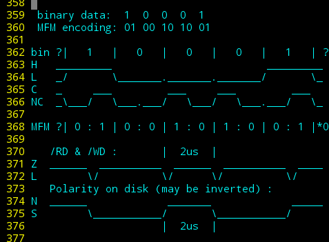
Most floppy drives use a method called Modified Frequency Modulation (MFM) to store binary data-bits on the magnetic media.

This method encodes each data-bit into two MFM 'bits'. E.G. the data-bit '1' is always encoded in MFM as "01", the data-bit '0' is either stored as MFM "00" or "10", depending on whether this follows a '0' or a '1' in the previous bit.
This seemingly over-complicated scheme serves several purposes. First and foremost, it assures somewhat regularly-spaced transitions/alternating between North and South polarity on the media, regardless of the binary data stored. Thus, the floppy disk controller is able to keep its serial-data clock synchronized with the data-bits on-disk. Essentially, MFM encodes both the data-bit *and* the serial clock into each MFM bit-pair. This alternating polarity is also essential for the inductive read-head/pickup, which can only detect *changes* in magnetism.
Thus, MFM assures that even 1KB of consecutive 0x00's (e.g. after a format) will be stored on-disk as alternating between North and South, once for every 0-valued data-bit.
------
But, note, again, that data-bit '0' has two separate encodings "00" and "10". If MFM "0110" were written to disk (binary data "10"), we'd have a problem... and this is where things get a bit more detailed, and we need to take a step back and analyze what's actually being stored on the disk.
Each MFM bit represents a potential for transition in magnetic flux. Wow that's badly-worded. Let's try again.
Most any position on the disk surface can either be North-polarized or South-polarized. MFM assures that North and South alternate somewhat regularly. Great!
BUT, placing these opposing polarities too close together can cause problems. Maybe the read-head is too large, picking up two (or three?) polarities at the same time, unable to discern which it's reading. Maybe there's some inherent granularity* in the media? There could be many factors, but as I understand, it boils down to these "magnets," each one MFM-bit wide, attracting and repelling each other.
Here's how I understand it: If you place two magnets on a table, so their North polarities face each other, then those two magnets will repel each other, up to a certain distance, at which point friction prevents further repulsion.
Placing a weaker magnet's South pole between the two would probably reduce the effect, but not eliminate it. The two stronger magnets still repel, and placing a compass above the weaker magnet's south pole will still show a net North polarity.
(*Note that 'precompensation' is another topic entirely, but if granularity was a concern, precompensation wouldn't be possible)
Thus, there is a minimum space which can reliably contain two flux-transitions (three polarities alternating, NSN or SNS). That minimum space is two MFM-bits long, on the innermost track, where the bits are most-densely packed.

(binary values: High and Low. MFM values: Change and No-Change. Read/Write values: Hi-Z/floating and Low. Polarity values: North and South)
Anyhow, an MFM '1' bit does not correspond to a polarity on the disk, it corresponds to a *change* in polarity on the disk. A "change in flux".
And two changes in flux can only occur at greater than some minimum distance (2us on the smallest/inner track on a spinning disk). Thus, MFM encoding does not allow for a "11" pattern. The first data-bit '0' after a data-bit '1' is, therefore, encoded as "00" rather than "10", giving data="10" mfm="0100", rather than mfm="0110"; no consecutive '1's in the MFM encoding.
All That To Say: diskettes guarantee proper data-retention when each singular magetic polarity is at least 2us long, but also alternates regularly. And, MFM assures that.
-----
So, the shortest single-polarity magnetisation is 2us, two MFM bits long, e.g. between MFM="101" where the new polarity starts immediately after the first '1' and ends immediately before the second... "10" representing two bit-durations of the same magnetization.
The longest single-polarity magnetisation is 4us, four MFM bits long. (Not shown in the diagram). in the pattern MFM="010001" from the data value "101"... MFM="1000" representing four bit-durations of the same magnetization.
These two limiting-cases, obviously by-design, satisfy both the serial-clocking needs as well as the inductive pickup's needs. The latter being most important for my new PWM-data-storage method.
 Eric Hertz
Discussions
Become a Hackaday.io Member
Create an account to leave a comment. Already have an account? Log In.