-
Neuron-Firing?
11/17/2018 at 22:21 • 2 commentsI've only a tiny understanding of neurons, but as I understand a neuron takes in many [analog] inputs and "fires" when some threshold is crossed. The output is, essentially, binary... 'zero' most of the time, then 'one' very briefly during the 'firing' of an impulse.
Anyhow, I think what it boils down to is the *timing* of those singular impulses ('ones').
And... that's *exactly* what this storage-method is all about! Output consists of two impulses, the time between determines the value.
Have I inadvertently stumbled on neural memory?
(Thanks @Lee Djavaherian for the comment in the last log!)
-
Light-bulb current-limiter... Incandescent RAM?!
11/14/2018 at 20:34 • 12 commentsAs part of my house-battery charging system, I thought maybe to use a light-bulb, instead of a resistor, as the current-limiter.
Pretty simple, place lightbulb in series between voltage-source and battery.
The idea came to mind as I sat outside a physical electronics-parts store (they still exist!) contemplating worst-case scenarios and the supplies available. 80W, I determined, through something like 0.1ohms. None-a-dem resistors were *even close* to that wattage.
But, yahknow, lightbulbs are darn near a wire and capable of handling 100W. If powered normally, there must be *some* resistance, otherwise they wouldn't stop at 100W! But, last I recall measuring with a meter, probably 15+ years ago, the resistance was near zero. So there must be an I-V curve, their resistance must increase when powered... right?
And, that's exactly what I'd want; a higher resistance when my battery's really low, so my charging circuit won't blow my fuse, and a lower resistance when the battery is nearly charged, to cram in as many electrons as possible (again, without blowing the fuse).
Cool. And after finding I-V curves showing just what I'd guessed, I had it in mind to see if anyone's tried it... Sure enough. It was actually pretty common back in the day. And there's even a video of a dude charging a car battery from 240VAC, rectified, with nothing limiting the voltage/current other than a series lightbulb.
Not *quite* what I had in mind, but concept-proven.
I started thinking about it, though...
The I-V (V-I?) curves didn't show extreme cases, extrapolation was necessary for e.g. the resistance of a 100W 120V bulb running at 12V (nevermind the ~2V difference when the battery's nearly full). So, it comes down to buying a bulb and measuring.
![]()
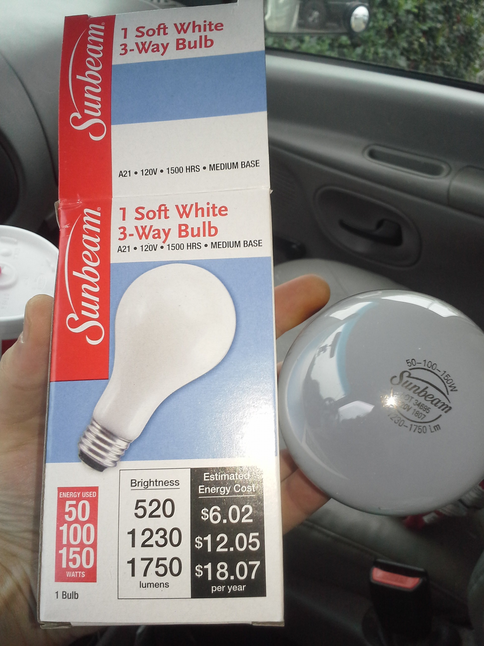
Figured this 3-way bulb would give me more options... (4!)
Measurements: ~10ohms and ~20ohms. Much too high for my needs. But, V=IR P=VI=V*V/R, R=V*V/P=120*120/100=14400/100=144 ohms vs 10 measured, *definitely* not a resistor!
Allegations are that the resistance increases due to heat... so, realistically, an I-V curve is a little misleading.
This be a strange device... Not a resistor, not an inductor, surely not a capacitor. What is it?
And what when 80W is run across it, but at a much smaller voltage? Maybe not possible, anyhow, its resistance would increase with the heat, thus the voltage-drop across it would also increase, and ultimately wouldn't allow high wattage at a low voltage.
Anyhow, I kinda thought, hoped maybe, the curve would swing down a little further, on the order of 0.1ohms woulda been nice. Am thinking a 12V bulb might have a lower resistance. Those high-wattage, low-voltage bulbs have beefy filaments. (How much light actually escapes a chunk of metal that thick?!).
And, this setup is probably much more like those of yore, when perhaps charging 12V car batteries from 15V-20V generators (depending on the driver/traffic) might've been accomplished with a series 12V bulb (NOT 120V, unless they really wanted a trickle).
Anyhow, high-wattage 12V bulbs aren't typically $1, and I figured out a workable solution with resistors and some less-extreme numbers.
But, if you're in a jam and only have 120VAC, a diode, and a 150W lightbulb, ~1A charge-current ain't bad. Hmm, maybe I shouldn't return this bulb.
Am curious about halogens, but that'll wait.
Also curious about the I-V curves when heat isn't a factor... e.g. a really short pulse... hmmm...
...
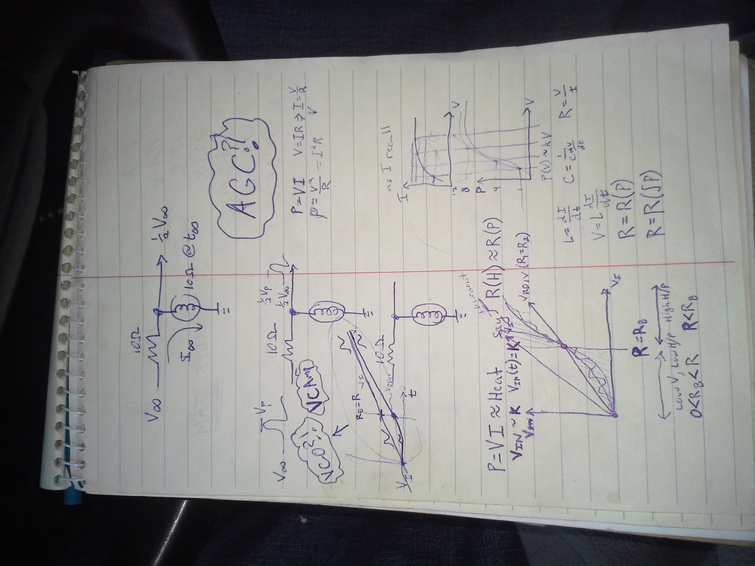
Actually, quite curious. A filter, laid-out like an R/C or R/L circuit... Short pulses would go through, until heated. Kinda like a charging capacitor..........
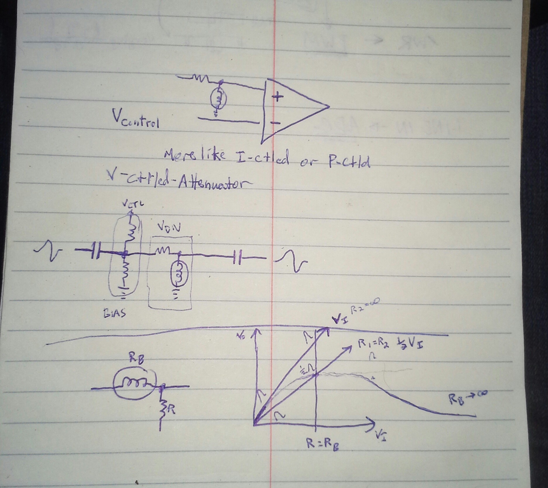
oh snap, what's this a voltage-controlled attenuator?
![]()
![]()
...
Search-fu is failing me... Seems there should be a circuit-model for these things, instead the best I've found is this:
http://physlab.org/wp-content/uploads/2016/03/Planck_ref8.pdf
Though, graphing the [very limited] points, it seems resistance is nearly linear with voltage.
Am darn-near certain I'd read about lightbulbs used as circuit elements in old-tech, just a few friggin' days ago. The obvious use as a fuse/current-limiter. Though, I vaguely recall hearing they were used in things like oscillators... and Not as an indicator.
I also recall reading mention of their use in synchronizing AC sources, If the phases are aligned, the bulb goes off, if they're not aligned, the brightness indicates the phase-difference. I definitely recall seeing this setup in a hydro with two generators, long long ago. Very cool, but not the same as using it as a passive component...
But those curves!
Seems unique, usable, if not *useful* in analog math, but I'm not finding it... Voltage-controlled attenuation is the best I've come up with so far.
OTOH, since heat takes time to build-up and dissipate, it seems this has similar characteristics as capacitors (storing electric-fields), inductors (storing magnetic-fields), and light-bulbs storing heat-fields. Current-memory, kinda like inductors, except with the opposite effect, resistance *increases* with current. Memory. Hmmm.
Friggin' Visual Data Bits! Like magnetic-core memory, or capacitive DRAM!
Yep... am already designing the read/write/refresh circuitry... relays? "Holiday Festive Lights"? Yeahp.
We're talking a frame-buffer *and* display in one.
A bit, maybe, like my history of abusing TFT panels ["avr-lvds-lcd"].
And, a use-case involving persistant-IR-imaging. Imagine placing your hand on a grid of lightbulbs,
-
Coding! Coding again!
11/14/2018 at 07:32 • 2 commentsHad every intention of launching right back into those code-changes/experiments today... Instead, the first few hours spent making my hokey 12V/5V wiring less delicate. Here's a tip: drill + zipties.
Also had a revelation... See, that 5V power supply was intended to drive the 'antPC' as well as peripherals (e.g. my old hard disk)... thus, all those high-power USB ports. And somewhere in there I had it in mind to use those ports to power my project[s] as well. Brilliant!
But reality set in... I don't really have any high-current USB cables to cut for power. Oh, those dollar-store cables claim to handle 2.1A, but have you seen how thin they are? It's prb 4V by the time it gets to the other end. Fine for charging a 3.7V battery, but probably not for powering a 5V floppy drive's motors.
So, then I dug around for long/thicker two-lead wires to wire right in to my 5V supply... and at the end of that I'd splice the 3.5in floppy power connector. Kinda hokey to have a special cable coming out of my PC for this particular project... But just as I started to cut the cord off a wallwart, I saw the most obvious answer.
A friggin' power-cable from an old ATX power-supply... yahknow, yellow, red, two blacks, several connectors for both 3.5in and 5.25in drive-bays. Yahknow, kinda like one might find attached to the power-supply inside their computer, and might use to power things connected to their computer, like... a floppy drive. So, now, the antPC has power for peripherals... like PCs do. And it's plenty long enough.
I can't tell yah just how much fight it took not to wire up that yellow wire, too. "I don't need it right now!" and "It'd be *easy* to do if I ever do." But, more importantly, I suppose, is that it'd be [relatively] unregulated, from a car circuit... 11.75V - 12.6V, when not charging... Those numbers aren't too bad, pretty sure I've seen the likes coming from ATX supplies... but 14.2 into a hard-disk with no backup, that's a little nerve-wracking. Better not connected, lest I forget.
Did I mention that this seemingly simple task of stabilizing my power situation wound up taking hours? Yeah, several paragraphs, here, just recalling.
...
And, one of the main reasons I undertook this 12V->5V endeavor several days ago, now, cropped up today... The [house] battery dropped too low for the inverter. My PC woulda suffered a power-outage, right in the midst of coding... but the 5V supply hung in there with plenty of time for a proper shutdown. YEAH!
...
And, yeah, I got a few hours' experimentation/coding in.
First experiment: remove varying data. Record the same value in every nibble on the track. An easy compromise from recoding to handle e.g. 2-value "nibbles", as described earlier, is to just record the value 0x0 or 0xf. DUH. and 4-value is just as easy, and so-forth.
So, writing all 16 values, one on each track, runs several experiments at once.
And... an interesting result: Silence and constant-brightness on the LED, as the track spins throughout the majority of each rotation... on every track... suggesting, possibly, the repeated values are being read the same. As expected. Possible.
However, equally-informative, maybe, is that the brightness of the LED changes seemingly randomly (and a slight popping-sound) once with each rotation. Plausibly right around the Index pulse.
Why?
Well, writing of PWM-nibbles is delayed until after the index pulse... and stopped as soon as it's detected. So, there's a brief space on every rotation, on every track, where there's random garbage from long ago. This garbage is unlikely to look much like a properly-formatted PWM-nibble... OTOH, it might slip through my limited detection-scheme. So, maybe a random value comes through there...
BUT, the proper nibbles are written everywhere else on the track, the same value. So, a slight blip near the index may be expected, but as soon as the proper nibbles are detected/read, the LED should show the read-back value as its brightness.
Now, I let it rotate five times, and every time it seems to grab a different value and stick with it until the next rotation. If these values were *similar*, it could be chalked up to measurement-error, jitter, slight variances in the rotation speed, etc. mentioned/hypothesized in previous logs, which is what I was intending to look into. But, for the most part the apparently-read value seems to vary dramatically with each rotation. (On some tracks! I'll come back to this).
So, it would seem what's happening is that it manages to see something that looks like a PWM-nibble in, essentially, noise, and yet does *not* see the ones actually-written?! Otherwise, I'd expect some *slight* fluctuation in the LED brightness as the disk spins, but otherwise expect the brightness to be pretty much the same value across rotations.
Now, oddly, some tracks *do* seem to have this effect... But these tracks only seem to have a *dim* LED (so is that values near 0x0, or 0xf?)
I dunno. I think what I'm seeing on most tracks is a single value being [mis]read, and none of the others "making the cut." At this point more information would be tremendously helpful, so I think it's about time for UARTing. E.G. Each rotation spit out the number of nibbles detected.
Of course, this is all hypothesizing based on the idea that my nibbles are written as I intended, and readback, too. And there was the issue of processing overhead, where merely inserting a 'validCount++' could trip things up. WEEE!
Oh yeah, did I mention that I pretty much scrapped my pvts? That was a lotta work now in _duds/
-
Reinventing my reinvented wheel
11/13/2018 at 06:39 • 0 commentshttps://hackaday.io/project/28345-floppy-bird/log/143840-wip-mfm-normal-diskette-data-storage
LOL.
So, the shortest single-polarity magnetisation is 2us, two MFM bits long, e.g. between MFM="101" where the new polarity starts immediately after the first '1' and ends immediately before the second... "10" representing two bit-durations of the same magnetization.
The longest single-polarity magnetisation is 4us, four MFM bits long. (Not shown in the diagram). in the pattern MFM="010001" from the data value "101"... MFM="1000" representing four bit-durations of the same magnetization.
These two limiting-cases, obviously by-design, satisfy both the serial-clocking needs as well as the inductive pickup's needs. The latter being most important for my new PWM-data-storage method.
Yeahp. I wrote that. More than half a year ago.
And... I kinda rediscovered the bold bit, the hard way, in October.
...
The other day I finally got back to coding. A key factor was replacing my constants and calculations, which originally used microseconds as units, with instead a new unit I'm calling PWM-Value-Ticks (pvt). Thus, soon, I can use multiple AVR-timer ticks for each pvt. The original design called for pvts that occurred at 16/us, which corresponded to one pvt per avr cpu cycle, when the timer ran with no divisor. Thus, 16 PWM values stored in 1us.
But, since the latest conclusions that maybe 1/16 us resolution might be asking too much of the floppy hardware, I figured on running early experiments with scaled-back requirements, thus, e.g. 1pvt=3cpuCyc, etc.
This'd give a lot more fine control for experimenting as opposed to merely changing the timer's divisor. And, anyways, since I'd done everything in us previously, and relied on 16 timer ticks per us in some calcs who actually need a specific duration, changing the divisor wasn't an option, either.
So, pvts it is for anything PWM-nibble-related, and us/ns for everything else (e.g. 0.8us max /WG->/WD).
And... we come full-circle to the bold bit... There really may not be much room for experimentation in the form of scaling back expectations, because, as I apparently was already aware of half a year ago, then had to rediscover the hard way, the inductive read-head surely places a limit on the length/duration of a single polarization.
There's probably a small range of pvt-durations which will work at all. And the effect of longer durations will likely look the same as the effect of too-short durations.
It may be the only real option is to scale back not the density of PWM-nibbles, but the *number of values* per PWM-data-chunk, using the same timing (buffer durations) as the original design. E.G. a two-value system (as opposed to 16) would basically be within the same timing-constraints as MFM, and should work. Maybe then try a 4-value system.
But...
This path goes back to original (us) times as originally intended, as opposed to pvts.
And, now, the math/constants need rewriting again, almost back to how it was.
D'oh!
And further, quite a bit of the as-is code is designed exclusively for a 16-value system, so got quite a bit of recoding (again) to change that.
Experimentally, it's *likely* 4us isn't the longest measurable single-polarization, just the longest *guaranteed* measurable. So, realistically, there are *several* factors needing "scaling-back" and experimenting. And, for some, "scaling back" may actually mean *increasing* flux-change density. Seems a bit counter-intuitive. But, I didn't just pull those original numbers out of my hat.
I suppose the next logical step, then, should be trying out a two-value system with the original mfm-compatible timings. That should function... once it's recoded. And all that other recoding for pvts...? Oy. PWM-Value-Ticks don't make an ounce of sense, here.
...
Realistically, I've run into scenarios like this a lot... basing constants and math on units, then later realizing I shoulda used different units. Maybe I should think of this sorta thing more like specifying measurements in a CAD system. You wouldn't specify the width of a doorway by measuring from the outside of the trim on the left to the inside of the trim on the right... wouldja? Not unless the doorway is crammed against a newly-installed wall on the right-side and the right-side trim's inside-edge is in fact now flush with the edge of that wall's sheetrock, butted up against it... and you weren't specifying the door-width, but the length of the piece of trim you need to buy to retrim the top! OY!
-
More progress in non-progress
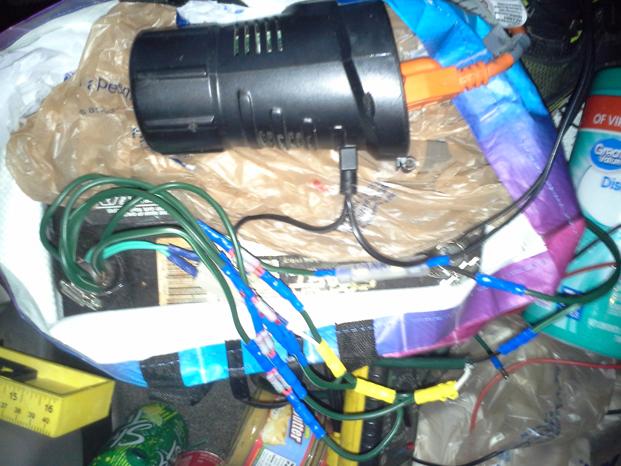
11/11/2018 at 07:20 • 0 commentsHere's my 12 parallel resistors from the last log. Yeah, it's a bit ridiculous ;)
![]()
And... all them (series!) crimps may be adding to the unexpected resistance of the last log. Oh well.
I've become a bit [too?] fond of barrel-crimps, recently. Aided by the fact Fry's had a deal which wound me up with a huge stockpile and variety, nevermind a bunch of surprising-quality sorter-boxes, for $4. (And, I've taken to investing in wire from extension-cords at DollarTree. One Dollah!)
So, then comes the next endeavor. My "antPC" (thanks buddy!) runs off 5V. So why run a 5V wallwart off 120VAC if I have 12VDC already? This is more than just an efficiency thing, when the voltage drops too low, my inverter just kicks out without warning. This is especially a concern when starting the engine (e.g. for heat, or a battery-top-up). Not the sorta thing you want happening in the middle of software devel... (nor, maybe, is seeing your breath).
So, I found a car-outlet 5V 6.8A USB "charger"... $9 for, really, a high amperage DC-DC converter, not bad. Especially considering I didn't have to order it. I figure since it's buck (rather'n boost) it probably will work even if the battery's *severely* drained. And, tests show it does, at least, keep running after the inverter conks out. So, when that happens, I guess, a little warning to properly shut-down, or start up the ol' engine.
This isn't just for the computer, though... Remember what this project was about? Yeah, I almost forgot, too. My floppy drive runs off 5V, as does (for now) the uC/circuit, programmer, etc. AND, I got a USB DVD drive at Goodwill, $5, so can finally add a few new movies to my viewage. AND I managed to salvage my old lappy's hard disk with a USB SATA adapter... (Thank goodness!). Both the DVD and HDD take more power than the antPC's USB ports provide, so 6.8A does the job of powering the antPC and the drives through a powered hub.
![]()
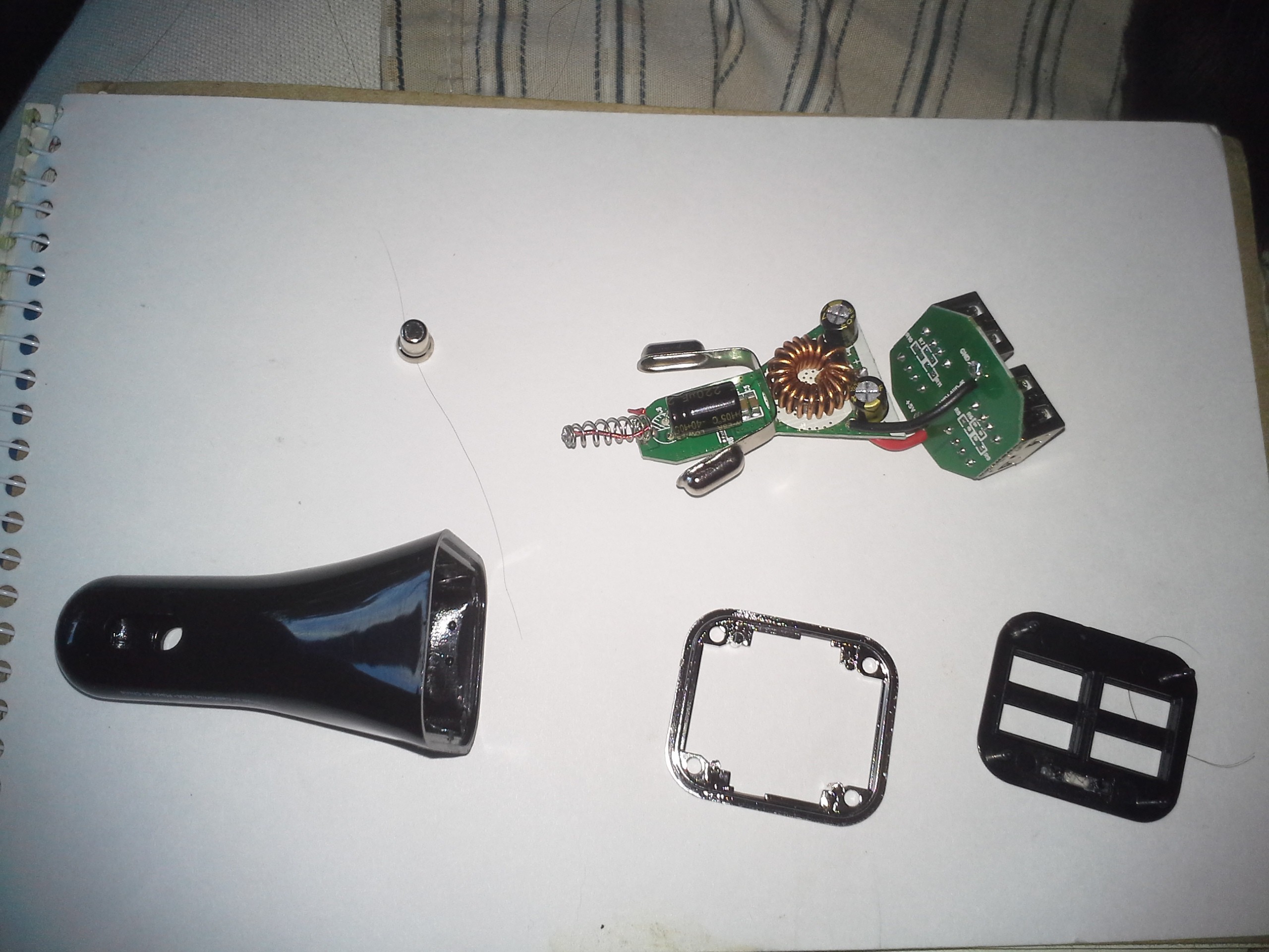
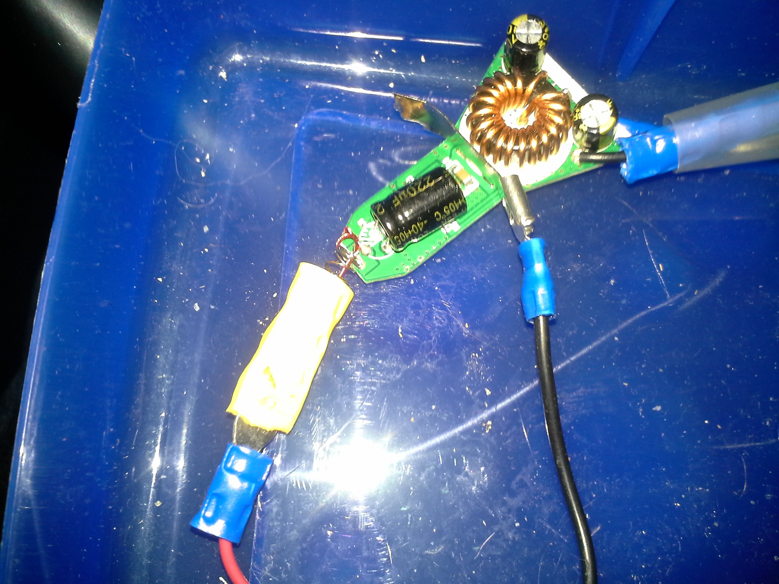
Here's a teardown of the charger. Pretty simple, really. And not too difficult to hack for my needs. 12V in, 5V out, (handy they had two boards with wire inbetween!) and some extra powered USB ports for "Dumb" things like the floppy-drive or phone charging.
(BTW, it's a Hypergear "Quad USB Car Charger" 12-24V in, 5V 6.8A out)
Had some challenges to overcome.
Like I said, I've become maybe too fond of these crimps. I started soldering when I was six. That *would* be my de-facto wiring technique. But, the solder-station is no longer always at-the-ready. So... carried-away with crimping.
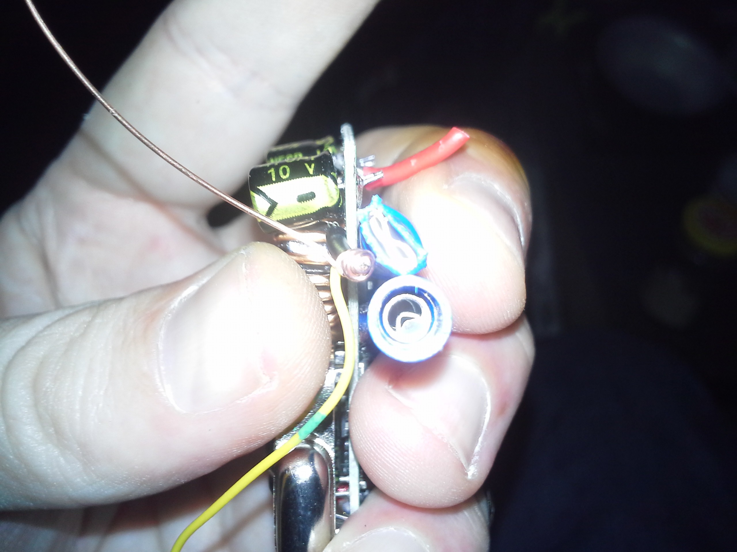
First challenge: the 5V wires are too skinny to crimp. And too short to strip really long and fold-over a few times. Too short, really, to even twist with some additional stranded wire. Too short to twist around a solid wire. Yep, I really thought this through.
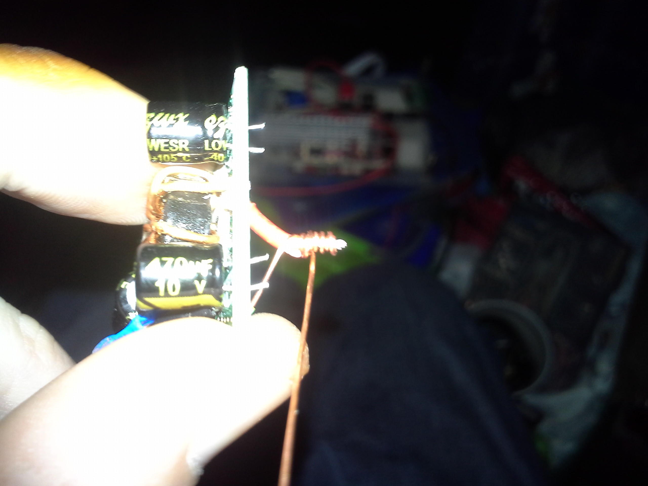
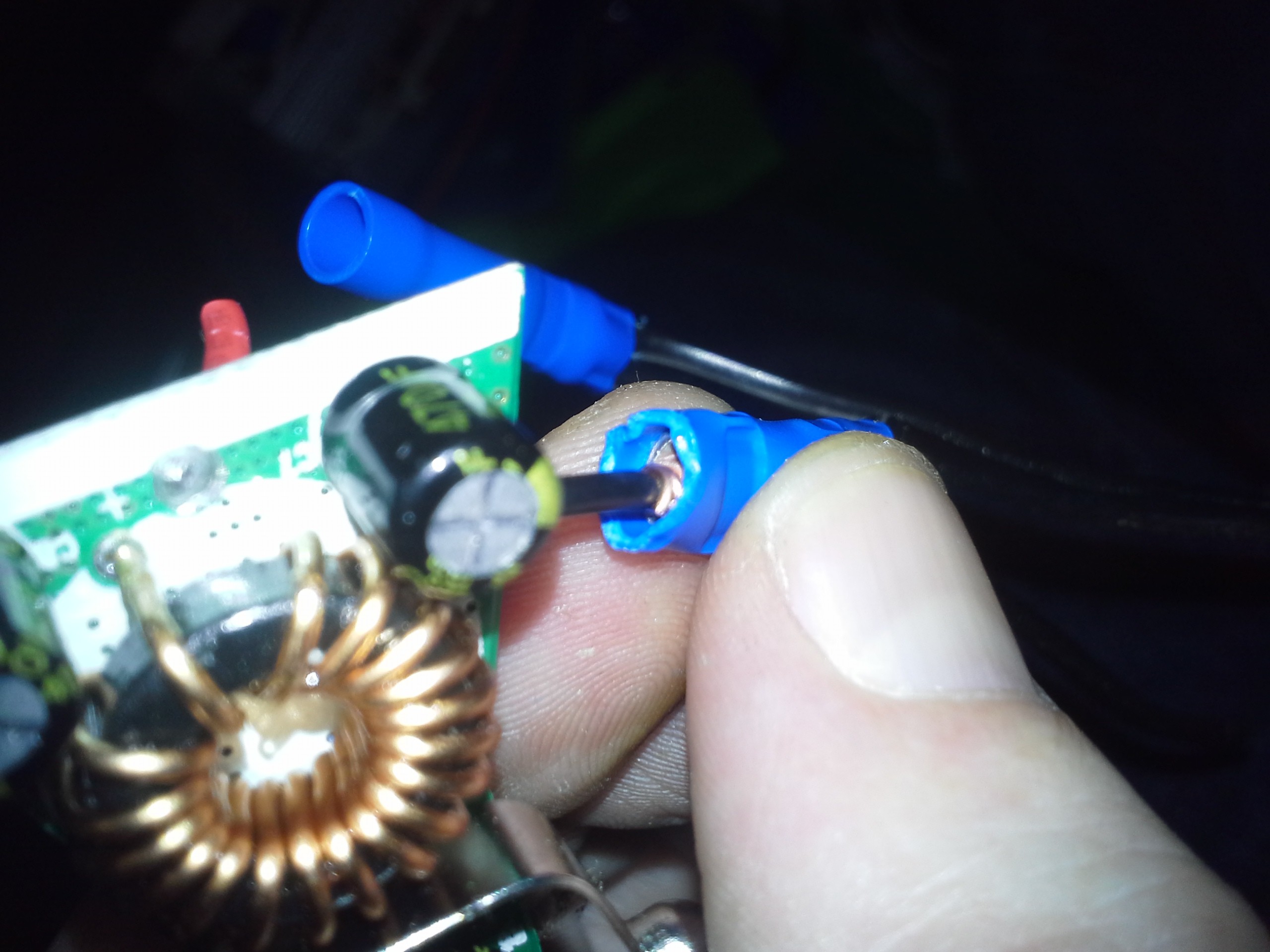
I'm actually quite proud of my solution. Wrap solid wire around it, like wire-wrapping. The solid wire is nearly perpendicular to the thin stranded wire we're crimping, so pull-out shouldn't be a concern. I tightly-wrapped two layers, then crimped. Rather, it's not particularly tight around the stranded-wire (that'd've just bent it!) but that each winding is tight to the next.
![]()
![]()
Worked so well, I did it four times.
("WTH, man? Just solder a new longer wire!")
![]()
Oh yeah, and it's too short to leave the insulation sleeve full-length. Another thing I ran into several times.
(Hey, note, I wouldn't be nearly so gung-ho about these crimps if I had a cheap non-ratchetting tool. I bought a cheap ratchetting one a while back. I think it was $15. It's really worth it. If just to prevent blistered palms. But, really, a ton of reasons.)
The next step was getting permanent wiring to the 12V... I'm sorry, but "cigarette lighter" outlets are stupid. Is there any plug that doesn't eventually push itself out? Again, not good during coding.
The positive connector is a spring. A wire is soldered to the end of the spring (where it makes contact with the outlet). At first I thought this to be an after-thought... Too much resistance in the long thin spring-wire? Why not just use a bigger gauge spring? Ohhhh... A looser spring is less likely to push itself outta the socket! Smart!
OK, how to connect with this thing? Maybe I can find a butt-crimp whose inner diameter is just slightly smaller than the spring and screw it on. Not quite. And crimping... well... I'd rather not damage that solder joint. (I think it's enamelled wire, crimping it may do no good!). Ahhh, insert into a big butt-crimp, and only crimp *after* the solder joint. Awesome. And the crimp deforms the spring and pinches it on the sides... no twist/pull-out. Great!
Found out the hard way, though, that my wire, even when folded three times, was too small. Now stuck with a crimp and nothing in it... Kinda looks a bit like a female spade terminal... Bam, male spade. Actually, male spades are too wide, so I used an eye-terminal, squished it to oblong, forced it in, then recrimped. Good-nough.
Finally the negative terminals... what the heck am I gonna do about them?! They're stamped sheetmetal with a large nub... Tried crushing that nub small enough for a butt-crimp, nogo. Finally just cut off the nub and was left with... duh... a spade.
![]()
(Did I mention I've gotten a bit carried away with the crimper? "When [all] you've got [is] a hammer, everything looks like a nail" I guess.)
So, all that wonkiness is... apparently... more reliable than some USB connectors and a car outlet.
But, I am pretty proud of the 'wire wrapping' technique I came up with... Am pretty sure that should be pretty durn reliable.
And the ol' devel system won't lose power when it's time for heat! And I finally got to watch the Garfield Halloween DVD. And I was able to recover my hard disk, photos, custom devel tools/environment, #commonCode, etc.
-
Physics?
11/04/2018 at 10:31 • 5 commentsDoes the "real world" align with physics for anyone, or is physics amongst the biggest hoaxes of all time?
The previous log detailed a string of luck, building a charger for my new "house battery".
Today I tired of its flakiness and invested in a lower resistance.
Believe it or not, there are still physical stores where such can be purchased.
I did math and came up with some extremes. Say the alternator's putting out 15V, and the battery's severely discharged at 11V... 4V difference. My lighter outlet can handle 20A... 0.2ohms should do well, and *way* better than the 0.75 from before.
(Oh yeah, so my 1:1 estimates last time were obviously disproven recently, as I drove at least a couple hours and barely got a half-hour's use. How'd it 1:1 last time?!)
So, the store's resistors are 2W max, and my extreme case is 80W(!)... I ain't using 40 parallel resistors, this is an extreme case.
Limiting factors included the available values and stock. I ultimately came up with 10 2.2ohm 2W resistors. In parallel with my two parallel 1.5ohm 7W resistors we should get 0.17ohms... close 'nough. Then I did some math, again, and these wattages should be fine for normal use. (The loaded inverter cuts out at 11.75, anyhow, not gonna drain it to 11! And a car regulator's like 14.2V, not 15).
So, I rig the thing up, 12 [big] parallel resistors, now... and try it out... This time a current-meter installed...
and I'm getting dang-near 1:1 again, right off the bat.
dang battery won't run the inverter+load, last I tried,... and it's charging at the rate I determined for the old 0.75ohm setup, (AND tested, that first time!)
OK.
So, there's that.
Now, watching the charging current, some other interesting findings... like... the heater fan drops the charging current, while driving 60MPH, by more than 10%. Headlights by 5ish. Brights vs. Normal, barely noticeable change in charge current. Braking... holy shizzle, 50% or more. 60MPH doesn't seem much different than 20, as far as charge current. In fact, I think it went *down* slightly after I got on the freeway from the parking lot. Oh, and jiggling the plug in the socket varies the current by about 10% as well.
I suppose with 0.2ohms and a couple/few volts, it should be expected that even a minor fluctuation in supply voltage would affect the charge current so dramatically... But... wow.
Definitely making me wonder if my alternator could handle a [nearly]-directly-coupled second battery. Or, I spose it's equally-plausible there's some resistance between the regulator and the accessory-distribution... bar(?).
Regardless, if my prior math was right for 0.75ohms, and with 0.17 ohms in actual resistors giving charge-currents calculated for 0.75... then there's about 0.6 ohms in the system. That seems like a lot to me. Think about the effect that'd have on heavy loads! 125W (output) inverters are pretty cheap these days, at 10A in, 0.6ohms would drop 6V?! and 60W lost in the wiring/connectors?! No, worse, 'cause now it's closer to 6V, so nearing 20A, and 120W in wiring! Som'n ain't right, here...
-
FlopProgress!
11/01/2018 at 06:15 • 2 commentsActually, none...
Due to a combination of factors unrelated to this project, specifically, progress on this project has been limited to the theoretical realm.
Well, that is progress, but kinda intangible.
----
I [finally] built a house-battery setup a few nights ago in a Wallyworld parking-lot. It musta been quite a sight to some folk in the lot; I felt a bit like Ivan in his B&I days. But for some weird reason that was when the friggin' project-energy kicked-in for the first time in weeks.
A buddy's car starter died a while back, but before diagnosis she bought a new battery, thinking the old one at-fault. I think/hope I helped ease her finances by buying the old battery. Not "ideal" for a house-batt, maybe, but a good starting-point, especially after a year and a half without (and several costly low-starter-battery scenarios).
So... first-things-first, a charging setup. For now, despite better judgement, it's getting charged through the lighter-outlet.
This project was one stroke of luck after another. It's kinda too bad I don't really have the energy to type-it-justice. Though, it stands as its own testament to that day.
A couple 1 .5ohm power-resistors I somewhat-randomly selected from my storage-unit a year ago were put in parallel to prevent blowing the outlet's 20A fuse. According to my preliminary calcs, .75ohms just happened to be almost exactly the right value for a worst-case extremely-dead house-batt.
Soldering wasn't in my mindset, and the stupid things' leads were *really* short, so eventually I realized that cutting the strain-relief insulation off one side of a butt-crimp would do the job quite nicely.
I planned to scrap another lighter-outlet for its battery-clips, but as I dug for my mis-placed butt-crimps I came across some hose-clamps darn-near exactly the right size for the battery terminals, saving the scrapping of a handy doodad which likely would still be useful in many situations, and now still-usable, even with the house-batt setup, and saving me from having to wingnut an oversized and unweildy wad of wires.
Between the car's outlet and the battery, I decided to use the wiring already in place for my cheapo--yet surprisingly powerful-enough for all needs thus-far--inverter. The battery, however, found its home, a while back, about three feet away... I tugged at that wire 'till it stopped, and at just the right length.
Continuing on, I rigged up the resistors to that cable, and sat for a bit trying to decide what wire I had for the Y between the resistors and the battery terminal... And, staring right at me was just what I needed; the inverter's original power cord had been cut and extended with an old three-wire AC extension-cord. When I did that, I left the third wire's ends dangling and unused with some intention of eventually using it for something I don't remember (maybe an 'inverter on' LED at the lighter-plug?). The exposed portion of that dangling unused wire was the perfect length for a V rather'n a Y, and with only a little more effort than stripping its ends, partially-strippable-enough to expose the center to be securely hose-clamped to the battery.
OK, Now I'm planning to attach the ends to the battery, and lo and behold the added-length, from the resistors and V-wire, is darn-near *exactly* the same distance as the battery terminals, which of course are already in-line with the path of the wire, and the battery's already in the right orientation. (Seriously, those things are heavy, and where it's located a 180deg rotation would require some effort. Imagine 3D Klotski with cinderblocks.)
OK. Wow, it's like this thing's meant to be!
SNAG!
Sh**. I'mma trip over this stupid cord, its stop-length, from earlier tugging, leaves it hanging about an inch off the floor. Tug tug, nada.
Wait, I've got it wrapped around the backside of a wall, passing across the doorway-floor, back-round to the front-side of the other wall. We're talking sheetmetal-thick "walls", here, not much length to be gained by not "crossing over" "diagonally" through the "doorway." BUT in order to get it to the backside of the first wall, it had to climb (and drop) about six inches. Avoid that, and... presto... dang-near exactly the right length to run flat across the floor.
OK, but I still haven't hooked up the inverter; I'd removed the cut-end, with its connector, from its earlier extension, and now it's just... surprisingly short. It'd be lucky to reach between the two battery-terminals, nevermind a couple extra inches, stripped, to clamp down. But, upon laying it out, sure-enough, it's again durn-near-exactly the right length to work after splitting the wires down the 'zipper', and even orients the inverter so the outlet and switch are accessible. (a 180deg twist in the wire, even really-tight and right at the connector, probably would've taken too much wire-length!). It'll do, and certainly well-enough.
Ah, but, yahknow... I'd kinda like a fuse between it and the battery. Its original fuse is in the plug, which of course is now used to charge the battery... I used to lug around my box of [cylindrical] fuses, but I haven't seen that for a while, musta-been re-storaged back in the broken-window-everywhere days. Now what?
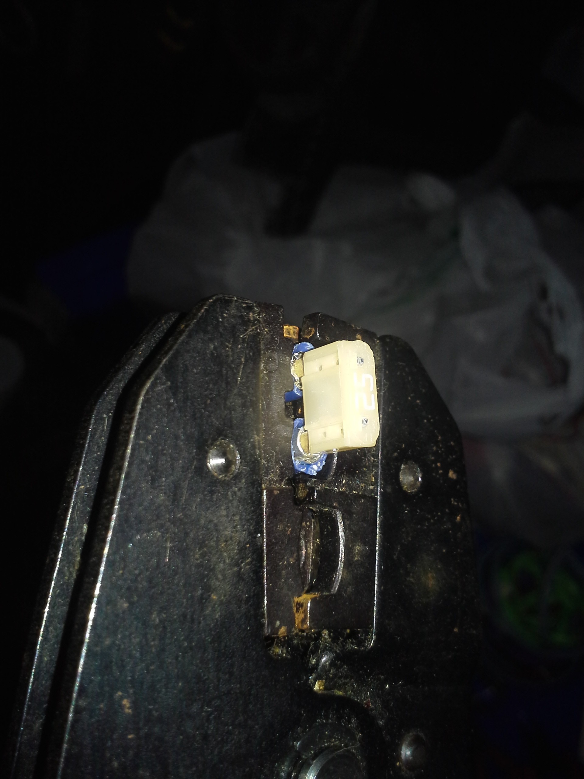
Oh yeah, I've got a box of itty-bitty car fuses. But how the heck am I gonna attach wires to those? My female spade crimp terminals, along with the rest of my terminal assortment, hasn't been seen for a while... probably wound up with the cylindrical fuses. And, besides, they'd make wonky-contact with these tiny-fuse terminals... Man that cut-strain-relief-insulation-butt-crimp technique with the resistors would sure be handy here... too bad the terminals are so close they'll get in the way of my crimper... Or will they?
![]()
Well, no sh**?! Couldn't fit much better if it was designed to. So what, I'm crimping a blue terminal in a red crimper... You never seen questionable crimping techniques before?
And, of course, now I need a short pigtail to connect to the hoseclamp... where'm I gonna find something like that? VVVVVERYYYYYY good question... And one left, perfect length.
Alright, time to clamp them terminals... I wonder if that *one* screwdriver-handled-socket I own, bought all them years ago to go with a stockpile of oversized 6-32 nuts I got from surplus, would work... that toolbox is *right here* and digging out all them other sockets and ratchets would be quite a racket. Bingo, fits perfectly.
Well, sh**... all that's left to do now is get on that road-trip I've finally got the money for today (thanks to a buddy who drove 50mi to give it to me!), and see if it works!
Quick-Math: 13.75 volts at my lighter outlet, 11.75V on the battery, 0.75ohms... V=IR I=V/R=2/(3/4)=2*4/3=8/3=2.6A?
I measured 2.5-2.8A from my load when I ran the batt down the first time. If I drive 60mi, in 60min, then I might get something around 2.6AH of charge, which would give me close to an hour of use. Weird how these numbers worked out practically 1:1:1.
...And, sure enough, I drove 50min and got about 50min of use outta the battery.
Of course, as the batt charges, its voltage increases, dropping the V-part in the equation, the charging current goes down... I can't expect 8hr driving to give 8hr use, though 3A*8H=24AH is surely within a car battery's capacity.
So, I guess, ideally, I'd figure out some way to charge it faster. 3A is far less than the outlet can handle. 0.1ohms seems a bit more worthwhile, pumping 20A at 2V difference. Though, it seems the 13.75V was idling, highway is more like 14.2, and now 0.1ohms blows the fuse.
So, longer-run, am thinking of other ideas. One possibility is a lightbulb instead of a resistor, they're made for high wattage, (20A, 2V, 40W!) and as the voltage across the bulb decreases, so does its resistance, plausibly keeping closer to a maximal charging-current throughout the charging process.
My first-plan was just a current-regulator, like can be made with an LM317, but I'm pretty certain 20A /40W would be asking quite a bit. Besides, they require 1.25V to operate, which may be treading in too-low-to-charge territory.
And then there's the fact that 20A is probably a bit much (though, am having difficulty figuring out what limits the charge-current in normal car-electrics).
And then, still, there's the fact this setup should probably be temporary. Amongst a slew of reasons, including safety and the fact 'deep cycle' batteries are better-suited, there's also the fact that there are more-established means of house-battery charging/isolation, and none I've found go through a cigarette-lighter outlet... instead connecting almost directly to the alternator.
Oh yeah, and a couple other things...
WHOOPS: the lighter-plug is live at both *exposed* terminals when pulled from the socket.
Don't leave it plugged-in when the engine's off.
And, is it just me, or is it not charging *at all* when idling? What happened to that 2V measured difference?
Oh yeah... and: It'll work, the inverter+load, while connected to the car-electrics... but it'll run the house-battery down first, then squeeze what it can outta the car through the resistors, not charging the house batt at all.
BUT. It was a pretty groovy "meant to be" endeavor that hopefully helped a friend financially, and otherwise was based entirely on the sparse parts at-hand just happening to come together functionally. And will at least be worthwhile during/after long road trips. That's an improvement over constantly idling whenever I need a few amps for hours-on-end.
[I idled for nearly three days straight before the Prize deadline! (I got about 8hr in naps in there, somewhere) Go away O-Zone! (and wallet, though surprisingly less than I imagined). As I said, my present situation makes running my starter-battery down too low (HOW low?) a costly experiment, to the tune of $50 each time. No joke. I seriously think some engineer needs some retraining if not fired for that. It could, in fact, be life-threatening under a certain, albeit unlikely, conglomeration of otherwise scary but non-life-threatening circumstances. Let's hope that never happens to anyone, or if it does that everyone walks away unscathed, and companies/engineers in that field a little wiser].
Happy Note to end on. Seriously, that project came together so smoothly, it was incredible. It'd almost be a shame to 'fix' the 'bugs' by de-sign-ing a replacement.
-
Low res... nope
10/28/2018 at 17:49 • 0 commentsThe key thing about this [original] design was that each nibble corresponds to a pixel. Each nibble stores the data, the sync, and the pixel clock.
So, if I keep with this design intent, then reducing the storage capacity, by increasing the physical size of the nibbles [e.g. by 8x], there inherently will be fewer pixel-clocks. Thus the display will have to be driven with a smaller resolution than designed-for.
Since the display is directly-refreshed (there is no scaler), this means there'd be a picture 1/8th of the screen-size either in the upper left corner, or filling the top 1/8th of the screen-height. Or maybe something inbetween, but still only filling 1/8th of the pixels. NOT stretched across the screen, like MarioThing, of the last log.
----
The original design-intent also included the idea that read-back could be entirely implemented with a handful of logic chips; four outputs of a counter, for instance, could be directly wired to the three color inputs (8 colors, one bit for each of RGB) and to Hsync.
The readback-logic has grown a little due to synchronization (determining which /RD pulse corresponds to the start of a PWM-nibble, and which to the nibble-value). But, still, the data is wired directly to the counter outputs.
Now there's some plausibility I might wish to do some scaling... Can that be handled with a minimal amount of additional logic?
Meh, sure... The counter is already clocked at 16x the nibble-rate, so a latch to store the data output, then the 16x clock could be used to feed the pixel clock. OK... Not bad.
So, say, we've managed to only store 1/16th of the data originally planned... Could stretch each image/data-pixel across 16 physical pixels. Vertically, the resolution would still be 160 pixels tall (image and data). Horizontally, the image would be 240/16=15 pixels, stretched across 240 physical pixels.
Were I to try to implement MarioThing, it could be done by storing every row 10 times to make for 16 image-pixels vertically. But, horizontally we'd be short an image-pixel. Meh. Anyhow, 1/16th of the capacity isn't set in stone. Maybe I could get away with PWM-nibbles that are 15x the length of those originally-planned.
OK, now it can still be done with a handful of logic. But, now, instead of driving the LCD's pixel-clock once with each nibble, it needs to be 15 times with each nibble... and... the logic increases in complexity, again. OY.
AND WHOOPS:
no, the counter is clocked *way* faster than 16x the nibble-rate,.. because of the start and end buffers. More complexity, still!
Fact is, I'm using a uC, due to supplies and space, so it shouldn't be difficult to pulse the pixel-clock pin 15 times after each nibble is read... but this all takes away quite a bit from the original intent of an LCD wired to a floppy drive through a counter.
So... I got a little carried away anyhow. Back to just storing and reading back PWM-nibbles containing audio, then going from there.
-
Two and Two, Twice!
10/27/2018 at 08:43 • 1 commentOK... somehow it's taken a year and a half to grab this stupid thing from its box in the back of my van, despite rummaging around it countless times, and realize that it needs to be *installed* in the van it's been riding in for a year and a half.
... two and two ...
..........
Now, that it's installed, I finally realize this is a great path for floppy-bird. (two and two x2). The stupid thing, as-is, with the old software seems to be refreshing at... dum dum dummm... 5Hz. Which, of course, is the rotational-speed of a floppy drive.
A few things... This guy, MarioThingMini, has an ATtiny84 driving the Sony ACX705AKM-7 display... As I recall, it actually updates fast enough to draw each of the 240x160 pixels differently, but even a single image-frame would max-out the onboard Flash, nevermind only having 512B RAM which is only enough for two lines of the 160. Nowhere near enough for a frame-buffer.
Floppy-bird, ideally, should store an entire 240x160 image frame on *each* of the 160 tracks on a floppy disk. So, using 16x16 sprites and a 16x16 viewing-window, as in MarioThing, would be a bit of a ridiculous use.
OTOH, the present scenario, with Floppy-bird, being as it is, that much storage-capacity may be a bit much to expect... At least until i have the time/money to do those characterization experiments mentioned in past logs... And what could I do with, say, 1/4th or 1/16th the ideal capacity? Low-Res... Duh. Maybe even as low as 16x16. Works in MarioThing!
.
Of course, part of the 'fun' of floppy-bird is the huge quantity of still-frames, and the weird visual-effects likely while switching between them (stepping between tracks). Not sure how that could fit with MarioThing which has realtime moving sprites and a moving camera window. Pre-rendered frames for every action? Seems a bit ridiculous, but who knows... Not like 'ridiculous' isn't this project's middle name.
Might be a path to ponder, anyhow.
......
Ooooh, it's slowly coming back to me...
As I recall, I fiddled quite a bit with the driving of this display. I think I wound-up refreshing twice for each image-change, then *not* refreshing at all until the next change (about 1/5th of a second later). This is a "display parallel interface" (DPI) raster-drawn display... It doesn't have a graphics controller, scaling circuitry, or any onboard memory. Every pixel must be drawn in realtime, in sequence (a refresh), and often enough to retain the image. Here's where I misuse TFT's inherent "memory" at every pixel. The image fades after about one second, so as long as you refresh at least that often, the image remains. So... There's no need to have a constant refresh-rate.
(Well, they say it's bad for the liquid-crystals. I can't vouch for that. I had another display running like this 24/7 for a year without trouble. its CCFL probably shouldn't've lasted that long!)
But... why was this relevant here...?
Oh yeah. For this display, anyhow (maybe many/most DPI raster-interfaced TFTs?), I think it boiled down to that there needn't even be a steady/constant pixel-clock frequency. I think I just stopped the pixel-clock after each refresh. And I might've even loaded a new color at the beginning of each of the 16x16 sprite-pixels, then strobed the pixel-clock as fast as I could [240/16] times before repeating the process. (it's been *years*).
That could probably be done with a simple arduino sketch.
(This might work with most DPI displays, but almost certainly not work with e.g. LVDS-displays nor probably DVI/HDMI. For LVDS, the pixel-clock drives a PLL, which requires a steady clock-frequency. Though, as I recall, I found tricks like these for those as well... imagine seconds-long 'porches'. E.G. Tens of thousands of "pixels" after the last drawn-pixel on one line before the hsync indicating the first pixel on the next.)
OY... what did this have to do with floppy-bird?!
...
Maybe it was just confirmation that the somewhat random data that'll come during a track-step should result in some interesting visuals, which I've been looking forward to. (rather than, say, the display's 'freezing' while awaiting resynchronization). And that, say, if the screen was only half-redrawn before a step interrupts, and, say it steps in slightly after the beginning of the next track's image, we'll probably get one image frame consisting of the top half of the last image, below that some random 'garbage' while the head moves from one track to the next, below that would be the *top* of the next image... Then, when the next track finally comes 'round to the vsync, it should resync, showing the next image properly on the next refresh. (as opposed, say, to it's 'scrolling' vertically, due to the excessively long frame-data received).
.
OH SH**
Previous comments about "most" displays probably need to be rescinded! I completely forgot about DE-Only displays, which pay no attention to Hsync and Vsync, and base all their timings on the dead-time between 'active' pixels (indicated by Data-Enable, aka DE).
And some non-DE-only displays do have similar effects with excessively long porches. Sh**. I vaguely recall *this* display having some oddities like that.
That shouldn't be a huge problem for this project, since odd-visuals are part of the appeal... But... It probably means I should just delete the majority of this post. Wee!
-
ferrofluid and floppy sectors
10/24/2018 at 16:50 • 0 comments![]()
Frankly, am kinda surprised the sector-gaps are so perfectly-aligned!
Floppy-bird
Use a floppy-disk as a multi-frame-buffer, store audio-samples, and increase capacity to boot!
 Eric Hertz