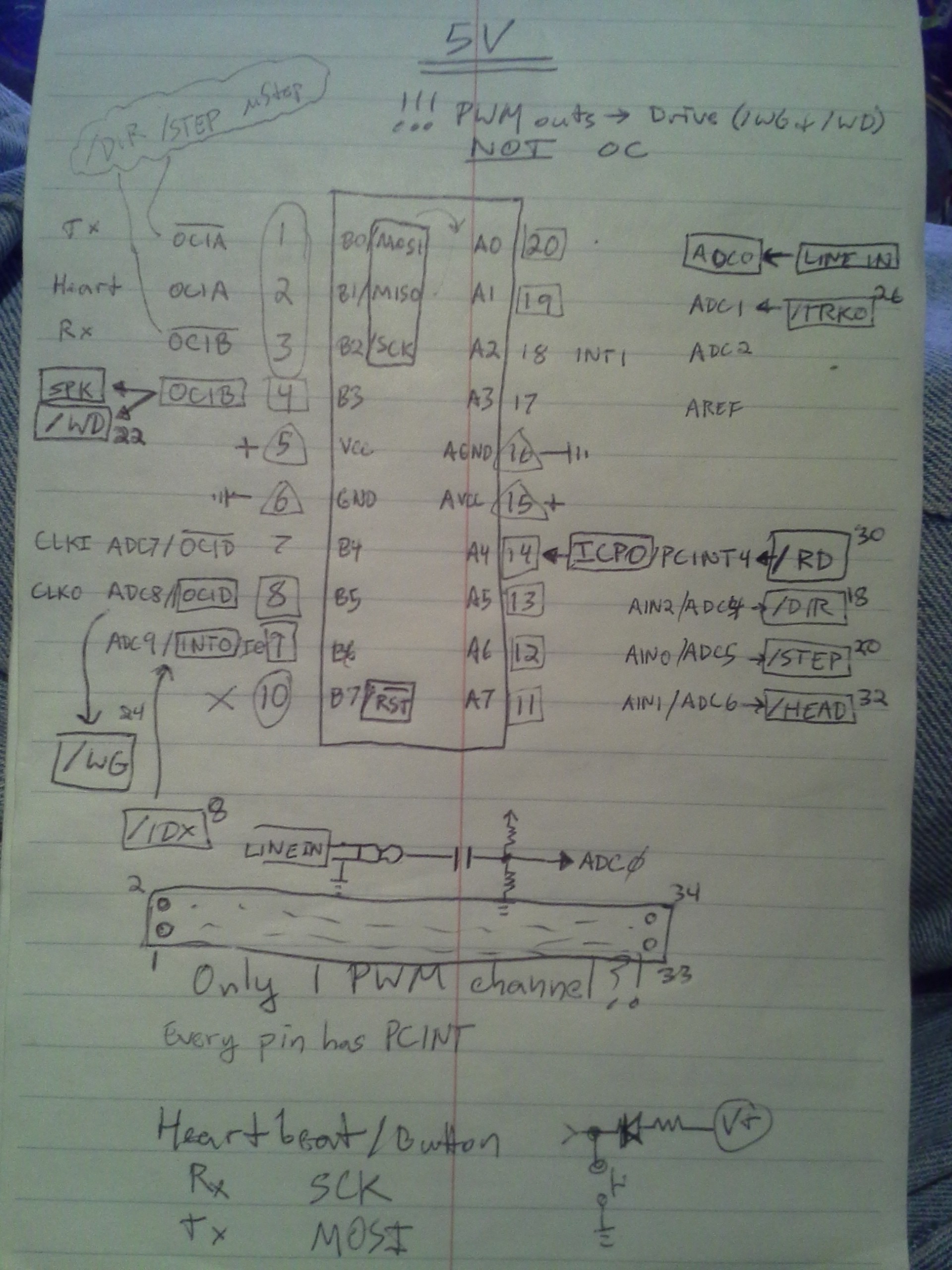
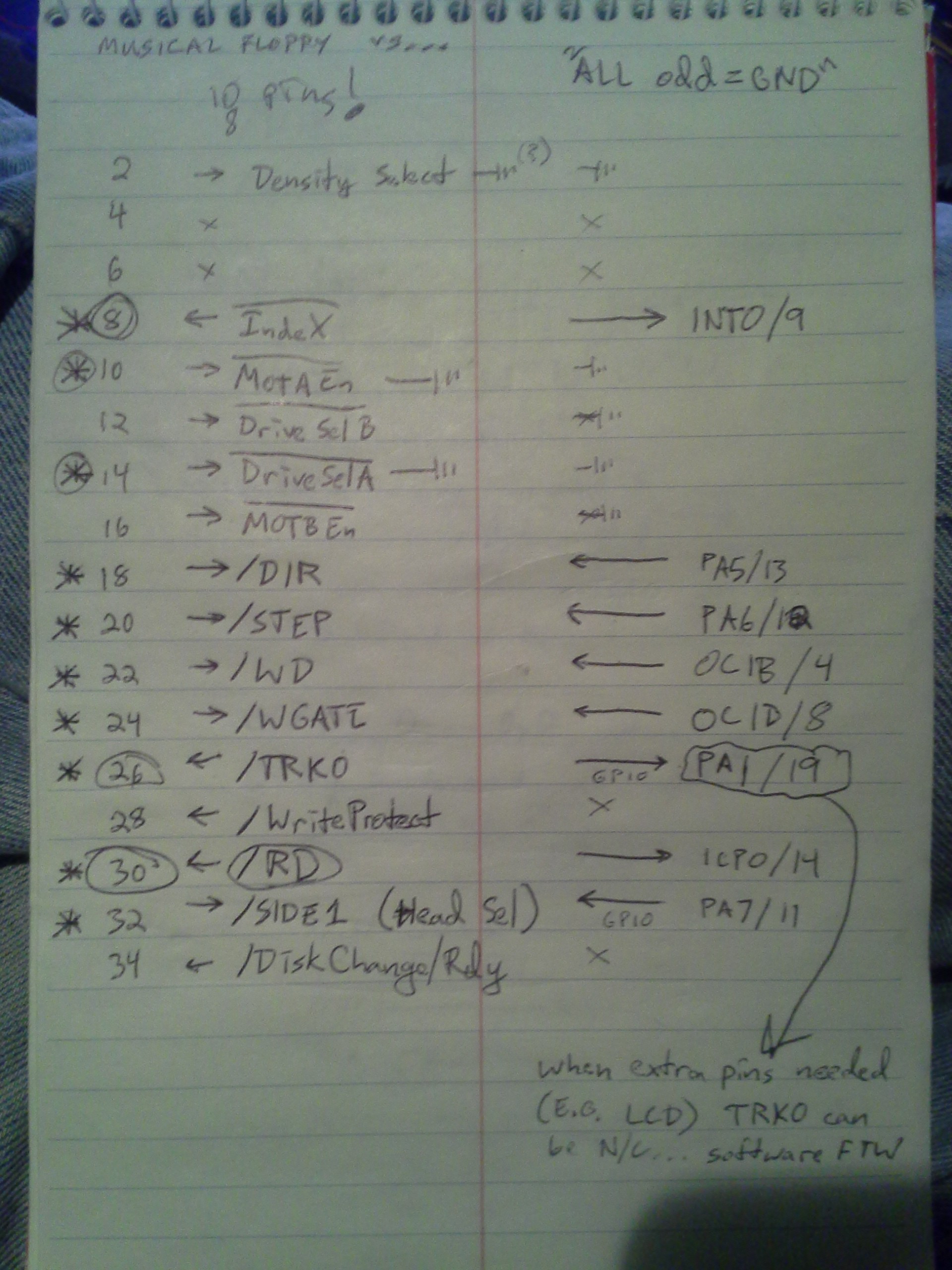
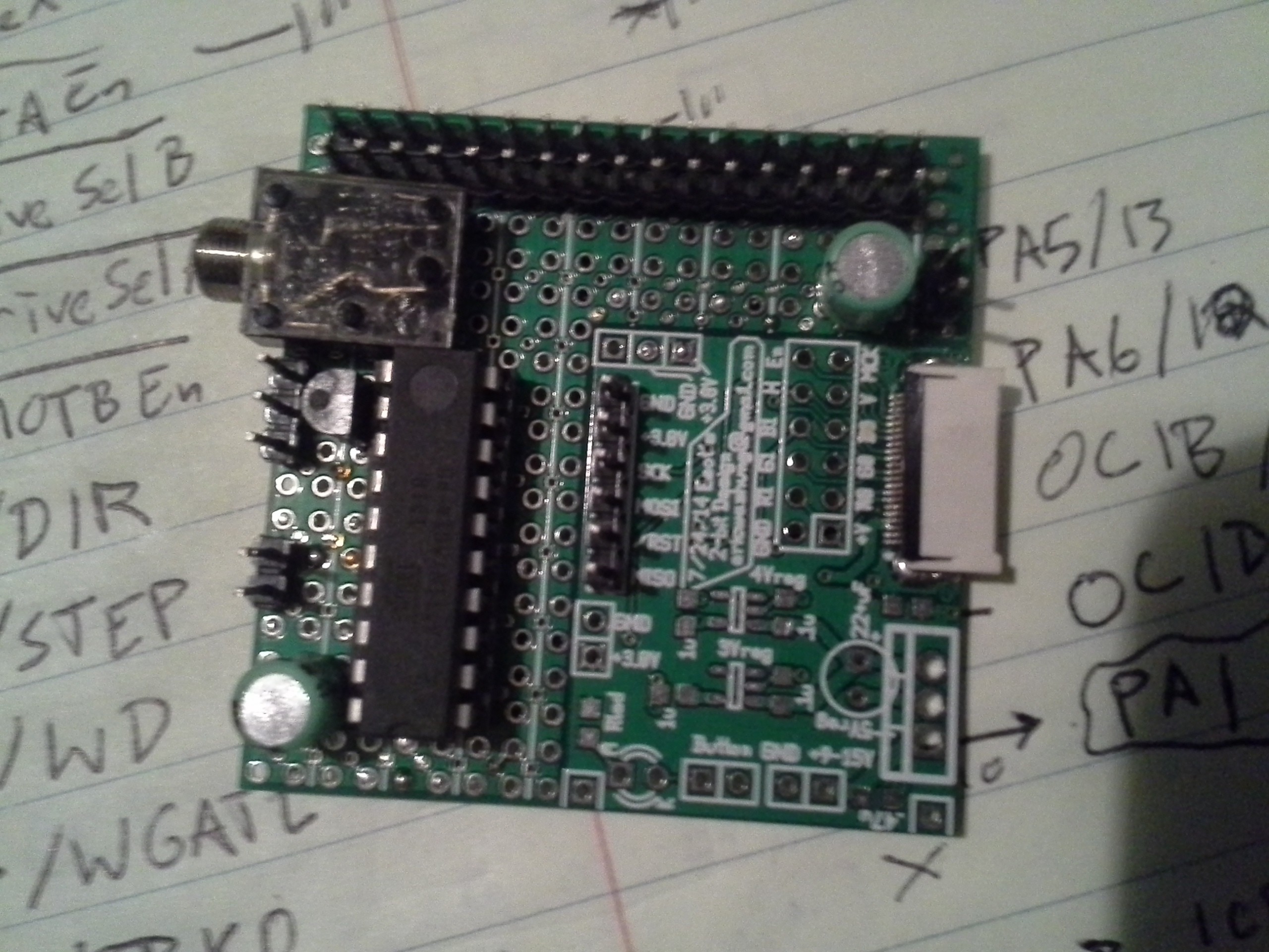
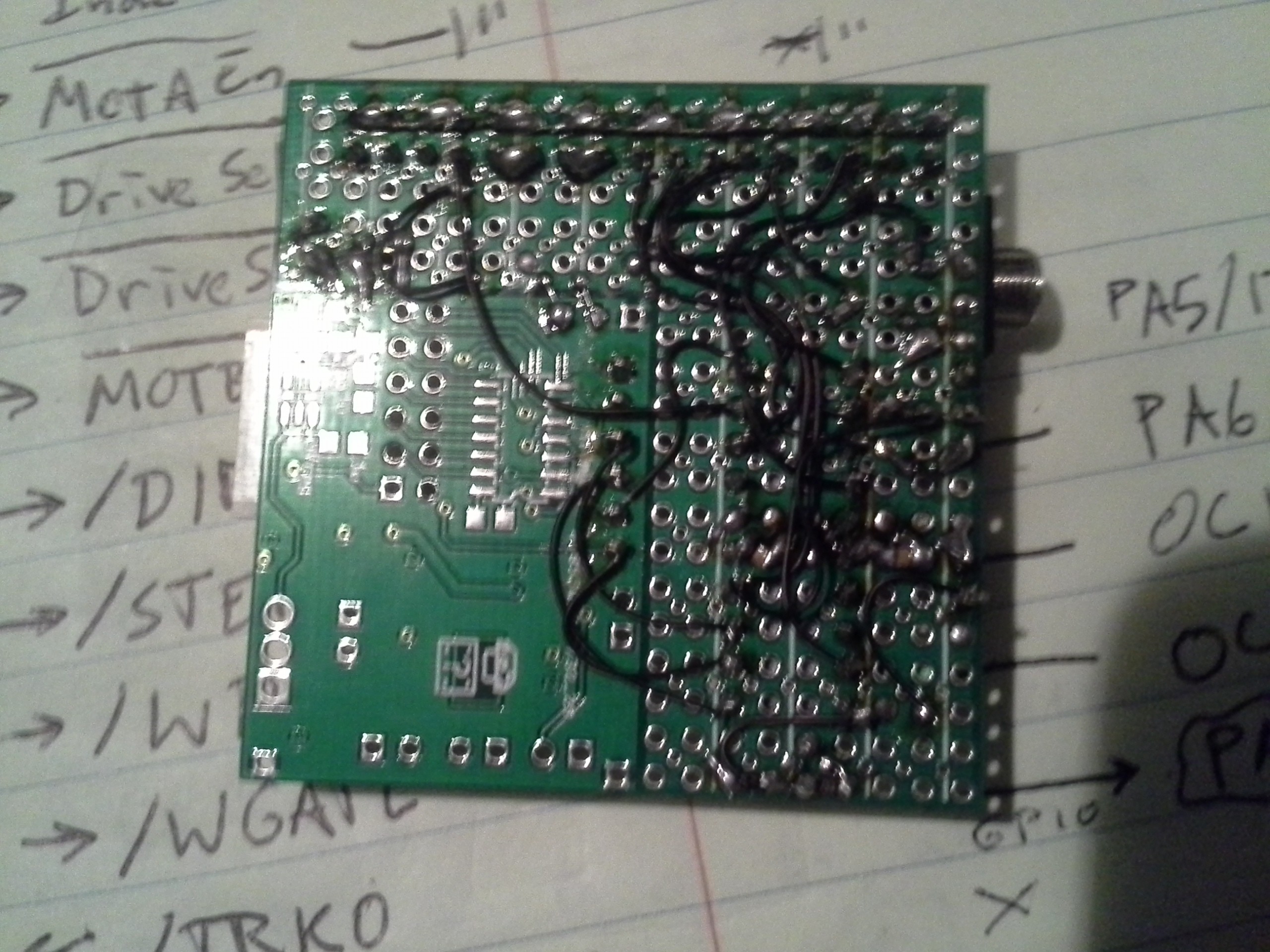
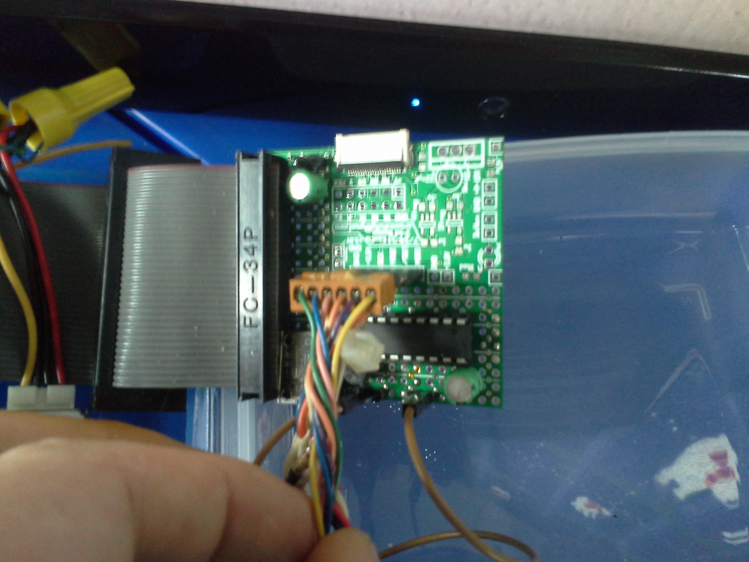
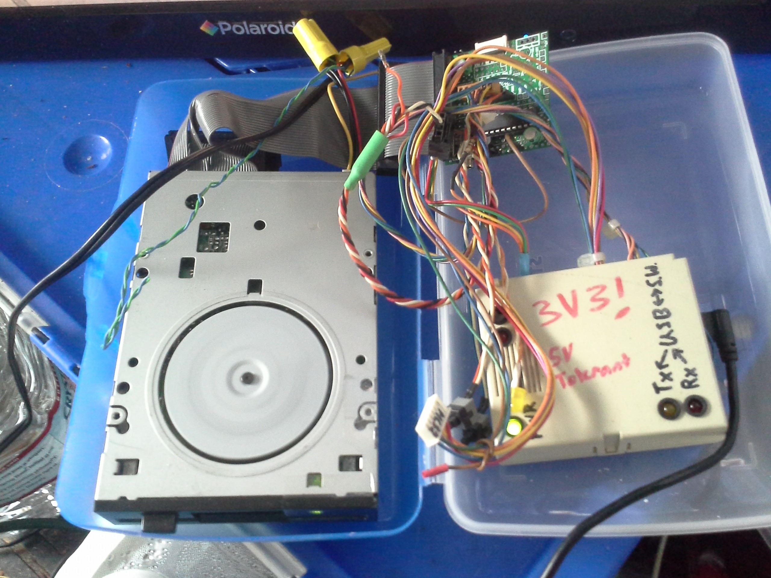
-
Strike 2
10/17/2018 at 04:44 • 0 comments![]()
ok, unanswered Q's from the last log... had to remember physics lessons from nearly 20(?!) years ago....
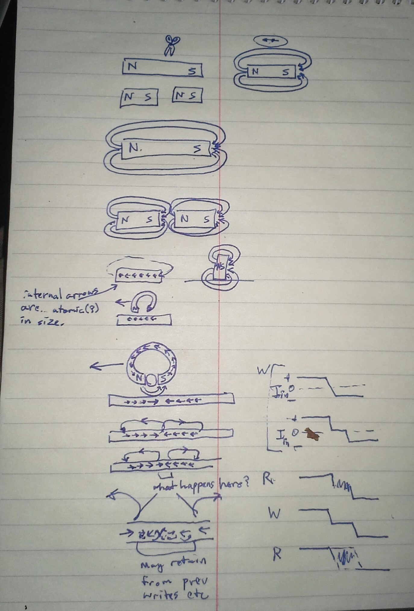
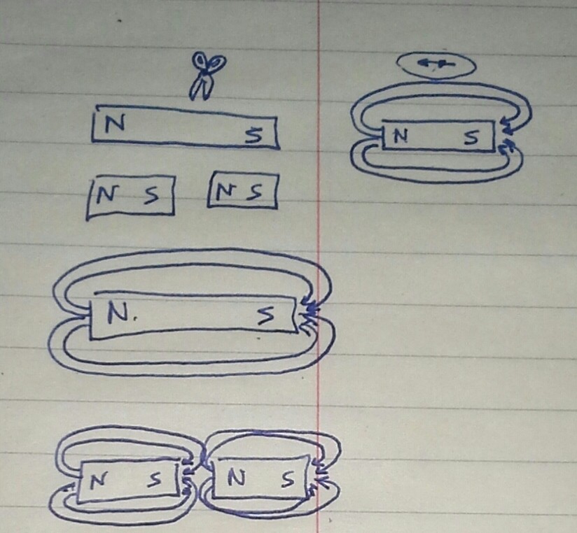
If you cut a magnet, you get two magnets.
![]()
The magnetizations are at an atomic or molecular level... each atom or whatever is a magnet, with both poles. This is demonstrable by, e.g. cutting a bar magnet into successively shorter pieces, all the way down to an atom-width, it'll still have a north and south pole (assuming the cutting process doesn't interfere!).
![]()
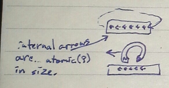
So, really, the only field lines are those extending from the ends of the magnet. Those between the molecules are so close as to essentially not extend outside the magnet. Thus, those have no effect on the R/W head.
Thus a long string of consecutive "bits" of the same polarity look like a long magnet with constant field-lines extending from the *ends* and wrapping around outside the media, in air, before reaching the read-head... right?
![]()
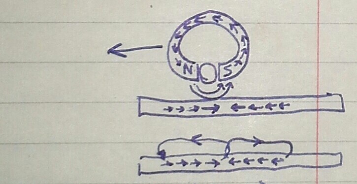
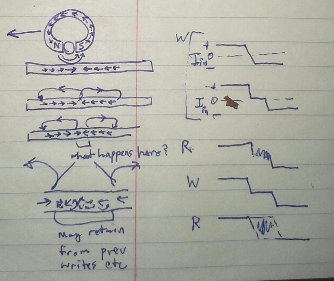
Note that the read/write head often has its gap filled with diamagnetic material to bend the field lines. Shown above is the write process. Below, the field-lines extending from the stored polarizations. Note, the short arrows in the media are Not intentionally drawn to have Any size correlation to the read/write head, nor to the size of a bit. Those arrows would more-accurately be drawn *tiny* in comparison, each, here, representing probably *millions* of similarly-magnetized/polarized particles. Flux, as I recall, is essentially the amount of field-lines (and direction) through some given area (e.g. the gap in the R/W head).
Floppy drives detect *changes* in flux, rather than an amount or direction.
It's impossible that a write-procedure could switch the direction of the electric current, and thus the polarization, instantaneously. "What happens here?"
![]()
The disk keeps spinning, meanwhile the write-head is essentially Off, at some point, and likely for some time, before ramping to the other polarity. Imagine "crossover distortion" from linear amplifiers. Also contributing: when the write-head has too little current to actually change the magnetization--during the ramp--for some time on either side of the crossover.
So, during the crossover/off time, the magnetic particles (that's the word!) on the portion of the disk spinning under the write head will not be written with any polarization. It will retain what was already there. (there is no "erase before write" procedure on floppies, unlike audio cassettes).
AND Strike Two for PWM-Nibbles.
Because...
During the crossover-time when written, the original polarization already on the media could be anything, could be noise, or could be same- or opposite-polarized from a previous write.
If same-polarized, the read procedure will detect a flux change not where it was written, but some time *after*. And now our measured PWM duty-cycle has increased.
If opposite-polarized, the read should detect the flux change when it was written (right?).
And, then there may even be plenty of room for numerous flux-changes to be stored and detectable within that space... There, I imagine, the read-back circuitry probably filters out repeated changes, reporting only a single low /RD pulse... ("0.1 - 1.0us" hmmm)... at the first flux-change detected. Much like a debouncing circuit for a push-button.
OK, so... I dunno how fast crossover is, but 1/16th of 1us may be asking a lot. So, it's likely my PWM-nibbles are being mangled here (as well).
Plausible Mitigation-tactics?
Write the same polarization *everywhere* on a track (erase) before writing data. Might be possible. But, now, the opposite-polarity case will read-back a different (though, maybe predictably) value than the same-polarity case. Maybe doable... May require some header-data to *determine* the polarity-sameness... as, there's really no way to choose nor read back polarity (again, only *changes* in flux are written/read with the /WR and /RD pins).
Maybe a track-erase could be *immediately* followed by a track-write? Though, as I recall, detection of the *index*, once per circle, causes the write procedure to abort... The erase-then-write procedure will probably require a pause inbetween, disabling then re-enabling the write process (via the drive's /WriteGate pin). So maybe no-luck guaranteeing the first written flux-change--after a full track-erase, indicating the start of the first PWM-nibble--will actually have the opposite polarization to that which was written during the erase procedure. In other words, it's probably aboht 50% likely the first flux-change written after an erase may get missed entirely, (thus, again, sectors in normal disk-usage have headers of repeating data that can be recognized by the controller, for synchronization).
Handily, Since each PWM-Nibble consists of Two flux-changes, the data-value offset (due to erase vs. write polarity-sameness) should be constant throughout each a single track (or write-process, should I eventually consider sectors). But unlikely to guarantee it to be the same on the next track.
Possible.
Also, this definitely brings to question whether the system could work with different drives. Could this synchronization process automatically determine each drive's "off time" and propagation-delay characteristics? (assuming jitter isn't an isssue) I think that may actually be inherent to the necessary offset-detection design, woot!
....
Another concern is related to the erase process. First-off, a /WD pulse is technically required within 0.8us after enabling /WG, and 0.8us before disabling. So erasing requires at least two flux changes. I haven't seen any requirement for minimal distances between those two. But a non-varying polarization throughout the majority of an entire circular track (after erase) may enter weird territory. Say a track was half-erased, maybe the field-lines then jump across the disk's diameter, rather than along the track! It may well just be not-allowed to write the same polarization for such long durations! And *that* too may bring into question the feasibility of long-duration PWM...
Also along those lines, an inductive read-head only detects flux-changes, but when the flux *doesn't* change for some time, will the sensitivity reduce?
The inductor's output will eventually return to zero current, rather than positive or negative. Then a polarization-reversal will result in a different current-change than where polarization-changes occur back-to-back. Maybe it'll get missed entirely, due to rail-clamping...
Or plausibly weirder, and maybe more likely, after the inductor-current returns to zero it'll be even *more* sensitive... e.g. fed into a comparator, a tiny fluctuation in current, say from external electrical interference, may cause a flux-change-detection, even though the actual magnetic flux under the read-head has been constant (and plausibly large) for some time!
And, in fact, I think I saw this in my experiments. I attempted to increase the "buffer" duration of the PWM-nibbles beyond my originally-specified 2us, in order to give more time for processing overhead. At 4us and above the recorded-data was completely lost in static, whereas at 3us, the recorded-data seemed *almost* recognizable. And recording a full track with a constant repeating PWM-nibble value resulted in near-silent playback from the speaker, as should be expected.
While that may be indicative of my 'head-zeroing' theory, it also seems a bit strange only 1us could have such an effect. MFM bits are 1us in duration. A string of up to <s>three</s> FOUR '0's is possible, as I recall, (binary '100' = MFM '10 00 01'. That'd be FOUR microseconds with nary a flux-change. Hmmm. And, of course, the '1us' specification is *ideal*, what when a disk is written on a drive spinning slightly faster than 300RPM, then read-back on one spinning slightly slower? 5us seems more reasonable, and probably no reason for tolerances even that tight. And, further-still, this assumes a drive that only works with 1.44MB floppies... what when a 720K disk is used? (Though, as I recall, they do spin faster, certainly not double-speed: 360RPM vs 300). The MFM-bit-rate decreases, (As I recall, 500kbps, though I dun think that math adds up) meaning those same read/write heads and associated circuitry need to cope with up to 8us non-changing flux... Anyhow, I should be able to expect more than 4us.
....
Also, a while back it was suggested to try these early experiments with bigger PWM-Nibbles... why start this project already pushing the limits? Indeed, that was silly of me. And Thanks, @Starhawk for reminding me that I could/should step back a bit.
The next step along that path was to use the next-slower clock-divisor for the AVR's PWM-generators. Whereas before I was using FCPU/1 (16MHz), the next step would be FCPU/8 (2MHz). That, I see now, might still be too fast for this early experiment, when bits stored normally are only guaranteed to 1us resolution. (And, stupidly, I wrote most my code with microseconds as my unit of measure in constants all over the place, a non-trivial rewrite).
So...this project's goals may need some scaling-back :/
Lessee, say I use 16us instead of 1us... maybe I can keep the buffer-lengths the same (2us on either side)... that's like 1/16th the capacity. Which... was originally-planned to be *just right* for my LCD display at 8 colors... 1/16th of a screen ain't much... Maybe B/W, half-screen... weee!!! Heh, then I could just use MFM. We'll see.
-
random Q's
10/16/2018 at 00:50 • 0 commentsDoes it erase first, then write?
Apparently not. I guess since it's binary, it needn't worry about 'ghosting' of old data.
Then what's with the "erase" head[s]?
Those erase (maybe 'crop'?) the edges of what was just-written. "tunnel erase". Apparently the read/write head is slightly wider than the data-track.
Are read and write on the same head?
For floppies and older hard drives, it seems so. Though that same head may have separate windings for read and write, the actual "horseshoe" of the two electromagnets is shared. Thus, there's no physical displacement between read and write.
....
Here's some references:
http://www.pcguide.com/ref/fdd/constHeads-c.html
http://www.retrotechnology.com/herbs_stuff/drive.html
....
Random unanswered Qs:
How does it determine which polarization to write, when?
Best bet: it just toggles... starting randomly, or maybe always starting the same. But the actual polarization at any position is irrelevant, as zeros are represented by no change in polarization, and ones are represented by a change (flux). Since individual bits are never modified, and everything happens in sectors, and since sectors always start with a long synchronization sequence, it really doesn't matter what polarization it starts writing with.
It's *highly* doubtful, to me, that it starts with whatever polarity was last-read... that'd be somethin'. But I'm pretty sure it takes a bit to switch between read and write, and by that time the head's already moved to the next bit. Further, it'd be plausible the old data would be more weakly-magnetized than the newly-written, even if the same polarity, which could be mistaken by the read-head/circuitry as a change-in-flux (one).
(This doesn't help my sectorless-single-nibble-rewrite ideas, but that was a far-aside)
BUT WAIT!!!
The read-write head is, essentially, a horseshoe-magnet. The media is written in the gap between the two sides of the horseshoe. Horseshoe magnets have *BOTH* North AND South poles.
A slightly different observation/question was answered (see Head Gap Width at: https://en.m.wikipedia.org/wiki/Tape_head) that the moving media receives the polarization from the trailing edge of the gap.
(Ahhh! That might help explain why it needn't be erased first, it receives the opposite polarization at the leading-edge and gets repolarized at the trailing edge.)
But, then, when the write process completes, won't there be a flux-change inherent?
Again with the fact of sectors written in one single pass, and a differently-defined 'gap' of repeating data written at both the beginning and end.
BUT, this may have some relevance to PWM-nibbles.... to be pondered.
....
What about magnetic monopoles? If the media is polarized by the trailing-edge of the horseshoe-gap, which is, say, South. And, say, the disk spins 1/4in, causing a North(?) polarization on the media for 1/4in... where is the corresponding South pole on the media? Wouldn't it have to be large enough, or strong enough, to match the total flux of that 1/4in North pole?
Opposite side of the magnetic coating? (rather than the plastic)? But, nah... because Perpendicular Recording is a much newer feature... (TODO look up). And am pretty sure the head-gap (the two sides of the horseshoe) is parallel to the track... (gah! is Perpendicular Recording perpendicular to the track ON the track's surface as opposed to perpendicular to the surface? TODO: LOOK UP!)
....
https://en.m.wikipedia.org/wiki/Perpendicular_recording
well shee-it... this can't be right... for longitudinal... then a flux-change would be measured at every head-gap-width *except* where two 'magnets' are butted against each other at the same polarity. If that were the case, we'd need separate read/write heads, with different gap-sizes, for different recording densities... and what about spinning?
Holy schmoly... dig this:
The larger the magnetic region is and the higher the magnetic coercivity of the material, the more stable the medium is. Thus, there is a minimum size for a magnetic region at a given temperature and coercivity. If it is any smaller it is likely to be spontaneously de-magnetized by local thermal fluctuations.
This might not bode so well for increased-width PWM-nibbles, which was an idea for experimental purposes...
Nonono, "Minimum size," not maximum... sheesh, brain.
But, maximum seems relevant, too... per my earlier thoughts.
-
Bit by the Jit[ter]?
10/15/2018 at 05:13 • 4 commentsJitter!
How'd I forget Jitter?
This, I'm pretty certain, is not typically specified in most era-datasheets. In fact, as I recall, it's [now] mostly only specified in *receivers*, as in "how much jitter will this serial-data input tolerate?" As opposed to "how much jitter is generated by this serial-data output?"
Wherein, there may be a potentially fatal flaw in my design-intent.
Which might explain why the best I got, last I coded, and recoded and recoded, was a bit of my recorded signal amidst a slew of "static."
Last-coding-status: I was pretty certain my use of C, rather'n inline-assembly, was causing computational-overhead that required more time than the 2us buffers available on either side of the PWM-data edge. So, toward the very end of that coding-endeavor, only a few hours before the deadline, I looked over [most] all the relevant assembly-listings... and... to my surprise, it seemed there should've been at least a few extra CPU cycles that went unused. And, having slept like a sum-total of eight hours in the past three days, chalked it up to... 'k-den' and "not enough time to investigate."
Thus, fate was the composer of my musical scores... Mostly-Static, sounding a bit like a metal band, maybe.
...
So, What is Jitter...?
Simply: It's a slight variance in the time when an edge occurs.
Imagine a perfect oscillator alternating between high and low with perfectly square edges (0ns rise/fall time!) at exactly 1.0000000000000MHz. Jitter is the slight variance around the times when those edges occur. They should occur at exactly 0.50000000us, but more likely they won't, varying by some tiny amount, say it's only 1ps... Then some edges will occur at 0.499999us and some at 0.500001us, and every time inbetween.
Overall, these variances don't add-up; they don't cause the perfect 1.00000000MHz oscillator to drift from 1.00000000MHz. And whatever's clocked *by* the oscillator is still being clocked at a perfect 1.00000000MHz.
So, I guess, Jitter somehow averages out to 0... I'm sure I've read folks' trying to explain it that way. Or, maybe it remains mostly-constant... a constant 1ps shift wouldn't affect the perfect 1...MHz clocking.
But, it's a problem when clocking and data need to be precisely coordinated. If your data edges 'jitter' too much, then they may make it appear the data bit belongs to the wrong clock pulse.
....
I've gotten a bit sidetracked, and it's important to note that I'm certainly no expert on any of this, this is how *I* understand it.
....
OK, so, with the 'constant' idea, earlier, it'd be easy to suggest that jitter could come from, say, slightly different wire-lengths between clock and data wires... And, indeed, that *may* be one source of jitter. Though, I'm not certain it technically qualifies, or whether jitter is some umbrella term encompassing all possible sources of... jitter...
But, as I understand it, 'jitter' is less deterministic. Sources include things like external noise, temperature variances, etc.
And, many sources are, I believe, a result of the driving circuitry.
Now, here's where it begins to apply to my floppy/PWM-data system...
Imagine, for instance, a typical inverter gate, e.g. 7404. Specs usually give things like tplh, tphl, tpd. The rise-time (tplh), the fall-time (tphl), and the propagation-delay (tpd). These numbers are spec'd as mins and maxes... and, for the most-part are considered somewhat stable, given a perfect power-supply, non-varying temperatures, etc. But, say your power-supply sags slightly because another of the six inverters in the chip is switched at the same time as the one you're paying attention to... Now the otherwise relatively-stable tplh of your inverter varies slightly. This gets fed into another inverter, coupled slightly differently to the power-supply, and there's a slight delay between when the first technically considers its output properly-switched, and when the second recognizes its switching threshold is met... Jitter can add up. 1ps becomes 2, and so-forth.
Here's another example I've run into: MIDI. Imagine numerous MIDI devices in a daisy-chain. Each has an input. That input is replicated through a Schmidt-trigger to the device's "Thru" connector. Sure, the output signal of each THRU has nice and square /edges/, but *where* do those edges occur? The Schmidt-triggers toggle high at some position on a shallow rising edge, then toggle low at some other position on a plausibly shallower falling-edge. (TODO: diagrams!) Further, despite all the efforts, those shallow edges aren't immune to ground-loops and other sources of interference, which may cause triggering at differing times.After doing-so several times (a long daisy-chain), the error adds up.
Now, say, a high bit surrounded by two low bits is actually skinnier than a low bit surrounded by two high bits. Even though the clock frequency/data-rate remains the same. And, in a system like that, UARTs, bit-widths can make a huge difference (TODO: diagram of start-edge vs. mid-bit sampling?)
That, I'm pretty sure, is also a source of jitter. And... it's pretty hard to spec.
.....
Now, how does this apply to my floppy/PWM-data system...?
Well, the floppy drive manuals I've seen don't spec propagation-delays, rise-times, fall-times, etc... And give even less info about the characteristics of the flux-transitions on the media, and how those correspond to data-output/input, timing-wise.
It's a bit of a black-box once a signal is written and read-back.
So, where does that leave me?
Because of the existence of write-precompensation, I'm pretty certain the black-box is non-discrete-time.
Similar is the fact that the disk may spin at slightly different speeds in different drives, and how the clocking-system of MFM, and the clock syncing mechanisms of the drive/controller, account for that.
But: An MFM bit is 1us... a slight shift in either direction, due to jitter, wouldn't affect its readability. That "slight shift" might be as much as 1/4 us and still be readable.
But in my PWM-data system 1/4 us is the difference between 0x1 and 0x5.
It may very well be that this hypothetical jitter exists only in the read-back system, or only in the write-system, plausibly not both... but there's really no way of knowing *where* or even *if* it exists without quite a bit of experimentation. And, if it exists (which, realistically it probably does), it'll most-certainly differ from drive-to-drive. And propagation-delays, etc.? Can any of this be characterized more thoroughly than the specs guaranteed for compatibility? Hmmmmmmmmm.....
The cat insists this is where I stop.
-
some notes on indiscrete timing
10/11/2018 at 01:11 • 7 commentsIn the project-description I try to explain the non-discrete nature of magnetic media, and do-so quite poorly. Here's a simpler example:
A 74595(?) shift-register can take in a serial stream of bits, and convert that serial stream into 8 parallel output bits. There are 8 discrete positions for a bit to be stored.
Similar to any digital-memory, like SRAM, etc. Each bit is discretely positioned on the output of some 1-bit-wide logic circuit, e.g. a Flip-flop (SRAM), or a capacitor tied to a logic gate (DRAM). Again, that same circuit is repeated for each and every bit.
In the case of a shift-register, we essentially have an 8-bit SRAM whose input is serial and output is parallel.
So, say you load the serial bitstream 01011001 into the shift-register's input, then the 8 discrete outputs will each show one of those 8 bits.
But now, what when you change that input bitstream to have a tiny pulse of '1' between the two zeros? It's not like, suddenly, a new output circuit/pin will be inserted between bits 6 and 7 to show that '1'.
This may seem ridiculous to harp on, but the fact is that magnetic media, signals sent down wires, even RF and optical systems are more-often-than-not treated as discrete-time systems just like that serial bitstream fed into that shift-register.
That extra '1' bit, discussed earlier, is considered a glitch in most storage and communication systems. Similarly, any value-change on that data stream at any time *other* than those discrete bit positions... (TODO: timing diagram). These, too, are considered glitches in most current systems (aka jitter).
Frankly, I think that's a tremendous setback to our technological progress (maybe that's a good thing?).
Similar to that 'glitch', even more similarly to that jitter, is the PWM-system I've designed, here... Feeding that *directly* into a shift-register seems a bit ridiculous... It won't work *at all* with the original MFM or RLL system, its shift-registers nor timing constraints. But it could work with the same (slow) technology available at the time, and so much easier with that available today.
Continuing with its seeming ridiculosity: For it to work properly fed into a discrete-time system like a shift-register (similar to the MFM design of the era), the PWM-Nibble--5us long, with 16 values stored in the middle 1us--would require a shift-register at least 48 bits long (more like 72!). And that shift-register would have to be 16 times faster than those in the original MFM/RLL system. Further, Only 16 of those 48 shift-register outputs would contain data. And that data, when packed in binary, would easily be represented by 4 shift-register outputs.
Speed-wise, as described in the project description, this system *could* have been achieved with the slower technology of the era... Using similar techniques as a 100MS/s oscilloscope with 50MHz ADCs, alternately taking samples. Or, much easier, by using timer-counters to measure the width of the pulse... As I recall, even the original 74163(?) could run at 16MHz. But, either way, there would be quite a bit more logic involved, and that wasn't cheap in an era where a Floppy Drive cost $200.
So, absolutely, this method seems *completely* ridiculous as a means of storing or sending binary data.
Except that magnetic media, fiber-optics, RF, etc. are *NOT* discrete-time systems, despite regularly being treated that way.
So, now we exist in an era where FAST DSPs exist, an era where FAST shift-registers can be packed in by the thousands in a tiny cheap piece of silicon... And yet, we're still treating things like magnetic media, optical media, and coaxial media as though they're discrete-time and we need to pack on them as many binary bits, in discrete binary forms, each occupying some discrete amount of time or space.
I think we've missed something.
This PWM-nibble method I've come up with may be still discrete-time, cramming 16 values in 1us. But, it relies *significantly* on the fact that the magnetic media is non-discrete when compared to the normal MFM or even RLL 'bits' usually stored, individually, in *discrete* bit-wide spacing. And the PWM system ideally does so WHILE maintaining the discrete-value benefits of our so-reliable digital systems today.
That's the idea.
And there's no reason to limit that idea to all-but-extinct floppy drives.
-----
OK, as an aside, it *just* occurred to me how much this system is similar to my project AVR-LVDS-LCD (todo:link github?)... Wherein I use an AVR's Fast-PLL-based timer to create PWM signals that correspond to serial data-streams to drive an LVDS/FPD-Link LCD.
Not a big deal, I just thought it was an interesting thing that these projects are so similar, yet seem so different.
There, I've managed to squeeze 48 colors, pretty close to evenly-spaced on a color-map, out of PWM signals fed into a *serial* input expecting sequential binary data-bits. (Todo: timing diagrams!). As well as sending proper pulses for Hsync, Vsync, and Data Enable... And this from the PWM-output of an AVR running at 1/4 the speed.
PWM FTW!
-
some photos, etc.
10/08/2018 at 14:15 • 0 commentsAudio and code uploaded, see this project's "Files" section.....
![]()
![]()
![]()
![]()
![]()
![]()
![]()
![]()
-
It's On!
10/07/2018 at 20:08 • 0 comments![]()
It has been a very packed couple weeks getting this thing going... BUT it's going!
Lest I fall asleep and forget to update, here's the latest:
I'm now recording PWM-nibbles onto disk *and* reading them back!
There's a definite 'thing' with trying to do so much simultaneously with such limited resources... Each microsecond has 16 clock-cycles for the CPU to work with... in 5us per PWM-nibble we need to do quite a bit. Writing a nibble, for instance, requires updating the AVR's PWM configuration *twice*. There's a bit of math to be done, and looping/tests... a bit of overhead that should probably be written in assembly... which I'm slow-to-remember.
So, presently, I think we're not really getting a constant stream of data, there are probably some hiccups.
Hah! BUT... we don't Need a constant stream of precise back-to-back 5us PWM-nibbles, all we *really* need is precise timing between the start and "value" edges of the PWM cycle! The duration to the next nibble's 'start' is irrelevant! How'd I forget?!
Off To Work!
-
e.g.4: interleaving audio - 3 minutes on a floppy
09/29/2018 at 17:31 • 0 commentsNew idea....
This part's been discussed in previous log[s], but a little background before launching into my new idea.
I'm not certain, but it seems feasible that individual PWM-nibbles may be rewritten.
This is exceedingly difficult with normal MFM storage techniques, in part because even the slightest shift in timing might cause what appears to be a different bitstream than intended.
E.G. (neglecting MFM's encoding for a second, and merely taking into account that each *data* bit is represented by *two* MFM bits): Say you have the data 10 00 10 and want to change the 00 to 10. Now the write-head is *very-slightly* misaligned (to the right) with respect to the read-head, and instead we get the pattern 10 01 00. NOT AT ALL our intended 10 10 10. That spatial-shift to cause that may be only 1/4th of a bit-duration, the data may in fact be recorded correctly! It's merely slightly-shifted. (TODO, draw some friggin waveforms!)
(There are *many* other reasons why this'd be exceptionally difficult, but let's start with that.)
However, These PWM-nibbles have a very large spatial buffer on the trailing-end, in order to assure no two flux-transitions occur too closely-together as to interfere with each other. That's the trailing-end's sole purpose. It contains no data, and its edge, at the end, is really indicative of the *start* of the *next* PWM-nibble. So, realistically, that buffer could vary in length and not affect the stored data.
(Man, this could turn into a great write-up, with graphics... I think I did, sorta, in a previous log)
So, with PWM-data all that matters is the temporal displacement between the rising-edge at the start of the PWM-cycle and the falling-edge inbetween two cycles.
BAM: it might be possible to overwrite a nibble anywhere on-disk.
Sheesh, I haven't even gotten to my new idea for audio-recording. That starts NOW:
---------
Each track spins under the head 5 times per second.
PWM-nibbles are (presently) 5us long.
Somewhere in there I think that correlates to 200KS/s.
Audio CDs are only 44.1KS/s... so we could easily store nearly a second of audio on each track at nearly CD quality.
(Well, 4-bit, instead of 16-bit *technically*, but we're talking PWM, here, not Data, and there's nothing limiting it to 16 discrete PWM values *except* when used for *data*... And even there, I believe I'm being conservative. This then being somewhat of a discrete-time, analog-value system, when used for audio).
OK... but how do we get 1 second of playback from a track which repeats itself every 1/5th of a second...? (Yahknow, obviously I'm trying to do this in realtime, no RAM buffer)
So... simply, interleave PWM nibbles. The first cycle will store at nibbles 0, 5, 10... The second at 1, 6, 11... Third at 2, 7, 12...
Which is really only possible (recording-wise) due to the huge buffer at the end of each nibble.
It Might Be Doable.
Now, how does this effect our simple playback circuit (previously consisting of nothing more than a 7474 flip-flop and a transistor connected to a speaker)? We'll need to add a counter 74163, I think... Two, actually (maybe two 4017s would be easier). An AND gate... (with output-enable?) And a capacitor to hold the value at the transistor's base. Hmmm, *plausible*, anyhow.
Anyways, it's just another possible tangent. That'd give 80 seconds of recording time on each side, near CD quality, mono.
Lessee, 44.1KS/s * 2Bytes (mono) = 88.2KB/s, 1.44MB per disk, I think that'd only be 16 seconds if stored normally...
Of course what is this "near CD quality"?
Well, if we neglect the analog nature of PWM, and go back to nibbles, each PWM-nibble is 4 bits of data, so, I suppose a slightly different system could be desinged using 4 nibbles to make a 16-bit sample... then we're back to roughly 1/5 second stored on each track, so a little more than 12 seconds(?) of actual CD-quality audio per side, 24ish total... sure beats 16... but, again, no sector-overhead nor error-*detection* as on a regular storage method (MFM, FAT), so... those numbers don't actually sound all that impressive. Bah! But, all it takes for playback is a handful of TTL components, that's kinda cool, no?
And, if you wanna see the real numbers of this PWM-nibble storage method, look elsewhere in the past, (Project-Description? Log?) I think I came up with 3.2MB unformatted with PWM-nibbles, compared to 2MB unformatted with MFM.
And, again, I'm pretty sure I've been rather conservative in this design. 5bits, or even 6 should be reliable per PWM cycle, with a faster processor (I plan to use an AVR at 20MHz, leaving a 1cycle buffer between consecutive PWM-values).
-
music contest. -- DEADLINE APPROACHETH!
09/23/2018 at 01:31 • 1 commentUpdate: "DO IT NOW." Deadline in less than 2 weeks!
Further info/updates at the bottom.
===================================
FloppyBird is a two-parter...
The first, proof-of-concept, is to use my new PWM-nibble storage technique to store audio on a floppy disk. The planned 250 (as I recall?) KHz PWM for audio is probably a bit overkill, but it will prove the data-storage concept for the next part...
The second part is using each floppy-track as a framebuffer for an LCD. The new PWM-nibble data storage technique developed in the first/audio part of the project will enable enough data to be stored on a single track on a floppy disk to directly stream an image from the disk to a raster-drawn LCD, in realtime. Each PWM-nibble corresponding to a pixel being drawn (prb 8-color, leaving other nibble-values for hsync, etc.). Since a floppy disk rotates at 300RPM, the track will be read, repeatedly 5 times a second, refreshing the TFT's image 5 times a second, until another of the 160 tracks, each containing a different image, is requested.
OK
back to the music part, since that's the contest du jour...
I *might* actually get to this this month, maybe. And, I've a lot of ideas for taking it in directions irrelevant to the framebuffer.
E.G. each track could contain a 1/5th second repeating audio-sample, then each track (of 80/side) could correspond to a MIDI note, playable by a MIDI keyboard, etc. 1/5th of a second isn't much, despite far more than that in pure data-storage-ability, but I'm trying to keep this simple... or am I? Regardless, I imagine most effects to sound a bit like a bird chirping, so now FloppyBird has two meanings.
E.G.2 A funky sorta long-duration playback can be implemented by tying the Step input directly to the Index output. After a track is fully played-back, it will auto-advance to the next track. Recording this is difficult, due to the (unmodified) floppy-drive's onboard circuitry (see previous log), and playback would have notable distortion every 1/5th second as the head [may never] settles into the next track. Though, I am curious to hear that effect. And the playback system would require nothing more than a handful of simple parts (no uC for playback! But still need one for recording. Bah!)
E.G.3. (see the previous log) Microstepping could be a thing, audio could be recorded in a spiral... a uC is necessary... and for some weird reason I still insist on using parts from floppy drives, even though the drive circuitry itself will have to be modified. Simpler might be to replace some of that circuitry with custom stuff, dunno why my brain went the path of using *two* drives' circuitry. BUT: This path feeds into another separate project, which may prove useful in the field of data-recovery.
...
So, IF I get to this project in time, there *will* be a uC, regardless of its necessity. MIDI, recording-timing, plausibly microstepping... AN alternative *might* be to use the two-controller method with the auto-stepping method. sheesh. Duh. BUT I don't have my stockpile of parts, so uC it is :/
Anyhow. Got a lotta things going against me this month, project-wise... and to top it off, my laptop with all my tools and custom libraries won't power up. BAH!
MUCH THANKS to a buddy, here at HaD, (Buddy, wouldja like to be named?) who hooked me up with a custom-built "antPC" even more powerful, and far less power-hungry than the ol' lappy... Size and power are huge considerations, presently, and he solved 'em both, very generously.
So, First, a few potential paths to getting back to uC programming ability, none particularly speedy nor appealing. Guess that's what I get for never getting around to uploading all of #commonCode (not exclusively for AVRs) :/
Ve Shall See where/if this goes. On the plus side, I'm kinda, slowly as usual, building up to project-momentum again finally. On the other hand, there's surely more pressing things to be worked on. Conundrum.
---------
Update 1: What the?! I had it in mind that the music challenge ended *with* October['s end], not *early in it*.
So for anyone with the same delusion, it appears, actually, to end *with* the end *of the first week* of October! Like Two Weeks!
As @Sophi Kravitz's catchphrase, which indirectly brought this to my attention, says:
"Do It Now".
Crud, it's 4AM, can I start "tomorrow"?
-------
Update2: Since writing this, I've recalled that, indeed, I do have a couple older projects, with bits of #commonCode (not exclusively for AVRs) in 'em, up on github... and Long Ago, In A Lifestyle Far Far Away, I actually went to somewhat tremendous effort to make it distributable from projects like that!
Download project, type 'make delocalize', as I recall, and whatever 'commonThings' (aka libraries) are in that project will be installed in a central location for use with all/other/later projects on the system... wow, I was kinda smart once, maybe a tad... That sounds sarcastic because it is... at me. commonCode was always a background thing worked on, sporadically, alongside my actual projects that make use of it, and otherwise pretty much hides in the background, so I litterally had to remind myself that it's way more developed than I remembered.
------
Update 3: "tomorrow" has come and mostly gone. Spent the day trying to fix Lappy (my devel-system). Looks like the CPU fried, it's had fan and thermal shutdown problems since I got it... guess my last thermal-shutdown wasn't quick enough. Rare, in my experience, to find a socketted CPU in a lappy, helped with diagnosis, it's certainly shorted internally on the power rails. Fixing may be easy, but not likely soon. Hard disk may be OK! But my USB gizmo needs an adaptor to try it out.
"antPC" is likely to be the solution. commonCode extracted from an old project in the cloud, along with a bunch of apt-gets, should get my devel-environment going (TODO: Must locate wifi). That poor thing got a bit of a battering, though, so may be another full day or more just to get it running again.
BUT: I have actually picked up tools for a purpose other than van-repair for the first time in... maybe a year? This might actually happen!
Oh, and... as seems typical for me these days, A Bunch of trying to find things, meant digging thoroughly through most everything, finding some long-lost otherthings, a bit of reorganization, but most-importantly refamiliarization with where to find what I need when I need it; always a daunting task that delays many a project... Now it's done, this may actually happen!
-----
Update 4: six days in (!!?) and I've yet to get a computer functioning. MOST of today was spent looking for a friggin' heatsink. Who'da thought that would be hard? Especially at a friggin' Fry's! Seriously, just hand me an old dead mobo and I'll nab the heatsink from the northbridge. I even googled teardowns of LED bulbs.
Wound up at Goodwill with my eye in one vent hole and my phone's flashlight in another, peering intimitely into nearly every electronic device they had, and googling teardowns.
Luck struck with a Clear WiMax modem, I saw what looked like heatsink fins, but nah couldn't be so large as to occupy the entire width of the thing... Checked *everything* else before deciding to take a chance, and sure-nough, that's one durn-near perfect match for what I was looking for. I saw similar on a PCI card at Fry's, just before giving up after hours of browsing,.. almost ready to spend $20 just to rip it apart, but alas, it wouldn'ta worked.
Now, what on earth, though... The one I got interfaces with the PCB, not a chip, and the chips on the other side are tiny. And the CPU doesn't even have any heatsinking anywhere nearby... Weird.
Something I hadn't considered, in my goodwilling, that also turned out quite handy: The device's housing is a darn-near perfect fit for the guts of this "computer." It might be turning into a tablet.
Some dremmelling to be done before the heatsink will fit, gotta wait 'till daylight.
----
Update 5:
Apparently the friggin' CPUs of this era are.... *way* more tolerant to poor cooling than those of my experience. Remember when just booting into POST without a heatsink would cause a red glowing CPU death?
Well, sheeit. I had this guy running, sans-heatsink, for probably 20minutes, booted into X-windows, running terminal, checking CPU-frequency and throttling statistics (hint: /sys/ is another "new-handy", don't bother grepping dmesg), the blasted CPU was *barely* warmer than my finger... but, also running (4 cores!) at ~500MHz, consistently... No Throttling, though!
I then ran "while [ 1 ] ; do cat /sys/.../cpu0/...current_freq ; done" and watched as the CPU freq varied a bit, to roughly 800MHz. Still barely past finger-temp.
Finally, another simultaneous terminal running "while [ 1 ] ; do echo hello ; done" managed to get it up to 1.5GHz, and five minutes later I *think* it was maybe 110deg Fahrenheit. Warm, but not hot.
Alright, so it was still probably spending a lot of time in sleep-mode, waiting for the kernel and X to update the terminal windows, clearing buffers to make room for the next echo, etc... (right?) So, probably not a great test for number-crunching or whatnot... BUT it never throttled, and wasn't even hot, and plenty fast enough for productivity in VIM and probably the few seconds of avr-gcc I'll be needing, sans-heatsink.
So, what'd I do? Spent the rest of the day making a custom heatsink, only to realize much later, upon planning to actually mount it, that there's a *much* more logical way to have customized it. Then spending an hour or so figuring out those details, planning to discard today's work, before *FINALLY* piecing-together that I really don't even need a heatsink to do the long-delayed project at-hand! Weee!
Can I switch tracks that quickly? That remains to be seen. Stupid brain's on heatsinks and mounting-methods... Next step, I guess, is soldering up the proto; soldering and heatsinking are similar enough, I think I could make that switch tomorrow, but I need to figure out *what* to solder; pinouts, etc... That's an entirely different mental-task for me... the track-switch that is hard to imagine and kinda daunting. Not that I'm no good at that stuff *when* I do it, but that *switching* to that mental-mode is not an easy process. Like using RAM-Doubler or Swap Space; gotta dig it out of the really slow hard-drive, and cache it back into the faster RAM, but only after displacing the current skillset back to the hard-drive, before getting started.
I think I got it... mechanistry -> soldering Parts To Board (no wiring) is an easy-enough transition, then soldering PTB will indirectly refamiliarize myself with what needs to be wired-up... which'll help the transition to pinoutting... OK.
-
Two Drives for hack's sake
09/23/2018 at 01:18 • 4 commentsThis thoughtpath is more of a braindump for future project-ideas rather'n directly-relevant to floppyBird... But, even floppyBird isn't particularly-relevant to floppyBird, since this project-page is kinda a two-parter, with multiple tangents, anyhow.
A tiny bit of background:
The idea, again, is to record audio [samples] directly onto a floppy-disk. As I've imagined, the entire [simple] system, record and playback, would require little more than a PC floppy-drive and some simple circuitry, no microcontroller.
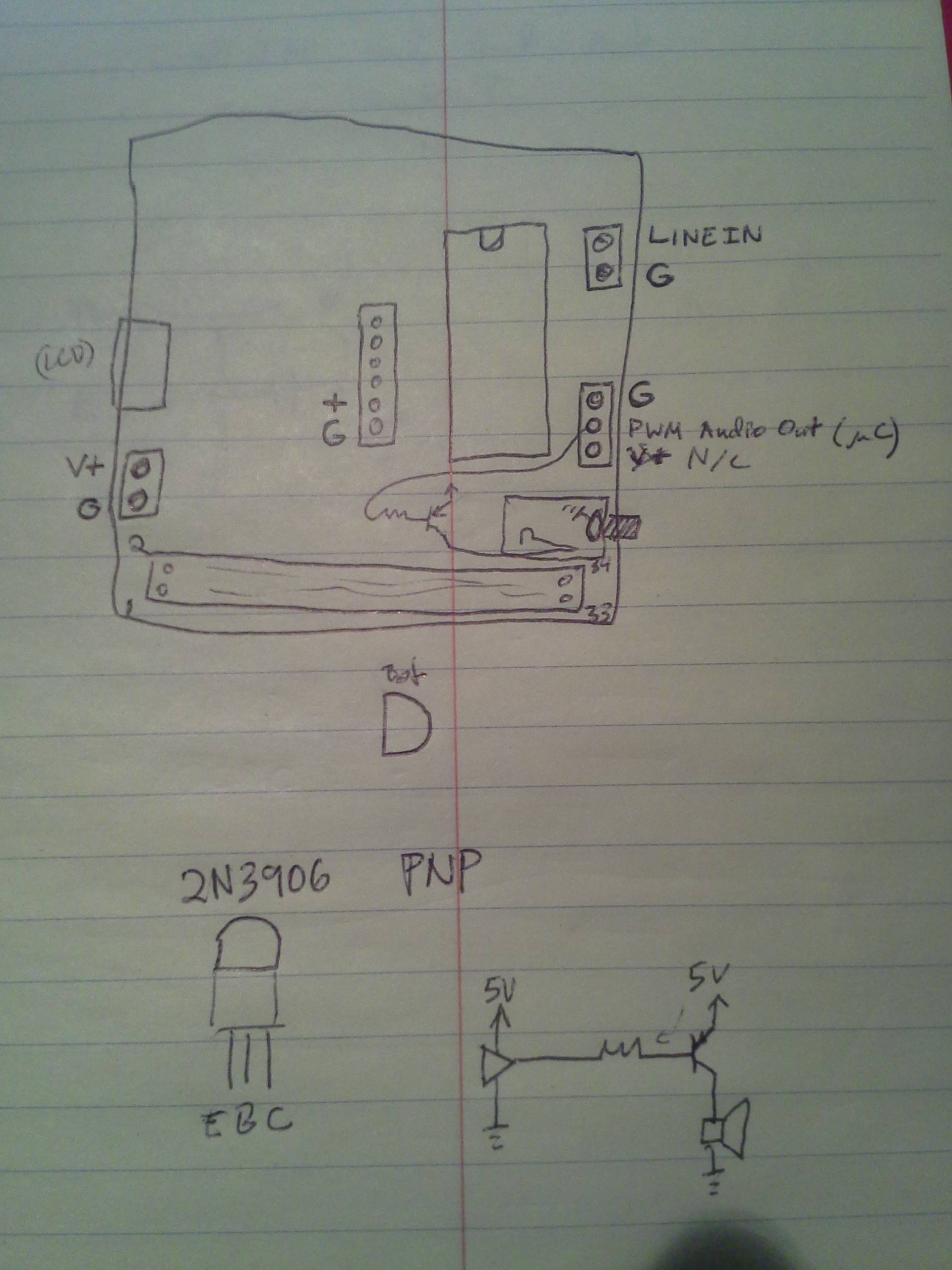
Playback from a single track/cylinder I've got down to a simple T-Flip-Flop, a transistor, and a speaker.
Recording, though, is a bit more complicated, due to the controller built in to a floppy drive. This controller has some protection logic to prevent accidental overwrites, e.g. if you try to record on a track for longer than a single rotation. Thus, timing of a few write-related signals is highly important. I'd thought it was only feasible with a microcontroller, but I recently had an idea.
If the controller used for writing was unaware of the 'index' pulse, and maybe some other signals, it would have no reason to go into what Imma call 'protection', and, thus, timing isn't critical.
One thought: Use a separate controller board, from a second floppy drive, which is *not* connected to the index sensor, nor the spindle motor. At that point, the controller might as well think the disk's track is *huge*, or even linear (like a tape). Thus, recording could be performed without regard to timing.
Index-pulsing is still useful, however, since a simple way to record/playback from *multiple* tracks, sequentially, is to tie the index output to the step input, making it auto-advance with each rotation, kinda like a CD or record (LP, 45, etc.).
Thus, using *two* controller-boards for recording: one handles the waveforms written to the disk, the other handles stepping through tracks and rotation.As an aside, this may also benefit my microstepping idea from a while back. (Probably discussed in my KayPro Floppy Recovery project).
Microstepping the read/write head may be possible with precise timing to the Step/Direction inputs. The Problem, however, is that each change to Step causes the floppy controller to wait for the head to settle into position on the new track before reading/writing is allowed. So, microstepping *between* tracks would cause the controller to continuously *block* reading/writing. So, keep the read/write controller separate from the step/rotation controller, and it might just be possible.(Microstepping between tracks is an idea I had for attempting to recover data from old disks which may have warped over time, causing oblong or off-center circular tracks. This effect is more common on 5.25in floppies whose circular spindle-hole may've been stretched by many insertions over the years.
But, microstepping in this case, for audio recording/playback, might be quite handy, as well. This'd allow a spiralling track, rather than dozens of concentric tracks. Thus, playback/recording would be uninterrupted with each rotation.
And, yes, I'm very aware that *without* microstepping, any audio recorded/played-back will be at the very least distorted with each track-advance. Thus, an idea, presently, to use each track as a repeating audio sample, 1/5th of a second in duration... selectable via MIDI) -
so, technically...
05/07/2018 at 00:33 • 0 commentsa normal 3.5in floppy disk holds 2MB. That's not due to rounding.
The disk spins at 300RPM, thus 5 rotations per second. The data-rate is 1Mb/s... but that's MFM bits, two of which make a data bit, so 500Kb/s of data-bits. Thus, 100Kb fit on each track, or 12.5KB. There are 160 tracks: 80 cylinders, two sides... 2 mega bytes.
1.44MB for storage is due to formatting. Sector-headers, CRCs, and a few other things. Most computers are capable of different formatting, at the hardware level, but software doesn't usually support that by default. Thus, it's more than possible to cram more than 1.44MB of user-data on a disk, but less than 2MB, by using a different format (fewer and larger sectors means fewer bits wasted on headers, more for data), *without* using compression.
But all that's moot to this project.
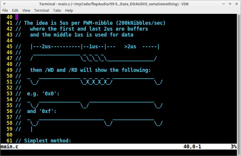
This project replaces MFM-bits with PWM-nibbles. Each MFM-bit is 1us long (1Mb/s data rate), each data-bit, encoded in MFM, is 2us long.
Each PWM-nibble, as I've currently defined it, is 5us long: four bits of data gets stored in that space.
Thus, in MFM, 5us would contain 2.5 data-bits, here it contains 4.
That's 3.2MB per disk, vs 2MB. Of course sector-headers can be equally-relevant in decreasing the capacity for user-data... but I see no reason why it would be more overhead than on an MFM disk.
That'd make the user-data storage-capacity of a PWM-3.5in floppy 2.3MB vs. an MFM-floppy's 1.44MB.
Significant!
Floppy-bird
Use a floppy-disk as a multi-frame-buffer, store audio-samples, and increase capacity to boot!
 Eric Hertz