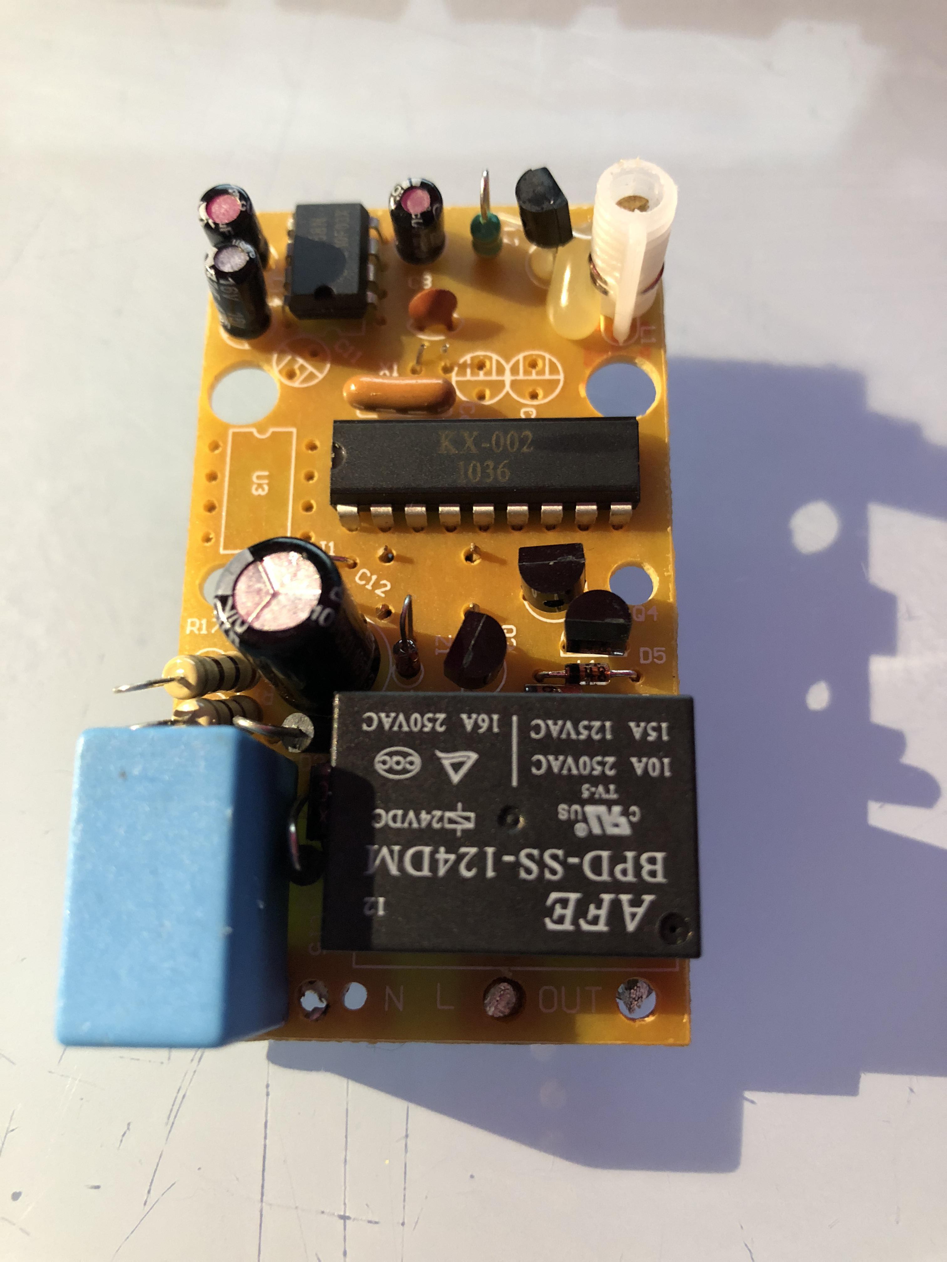
My goal is to design a drop-in replacement PCB that will fit into the six 'Status' branded sockets I have.
It will need to contain the following components:
- An esp8266 module with integrated WiFi antenna such as the ESP-12E. This is a nice and compact module with a surface mount design that required relatively few additional components.
- A relay rated for at least 10 amps at 230V
- An AC-DC power supply for supplying power to the esp8266 and relay. The it needs to be able to sustain up to 300mA for the esp, and comfortably another 100mA for the relay coil.
- A button for toggling the state of the switch
- A status LED
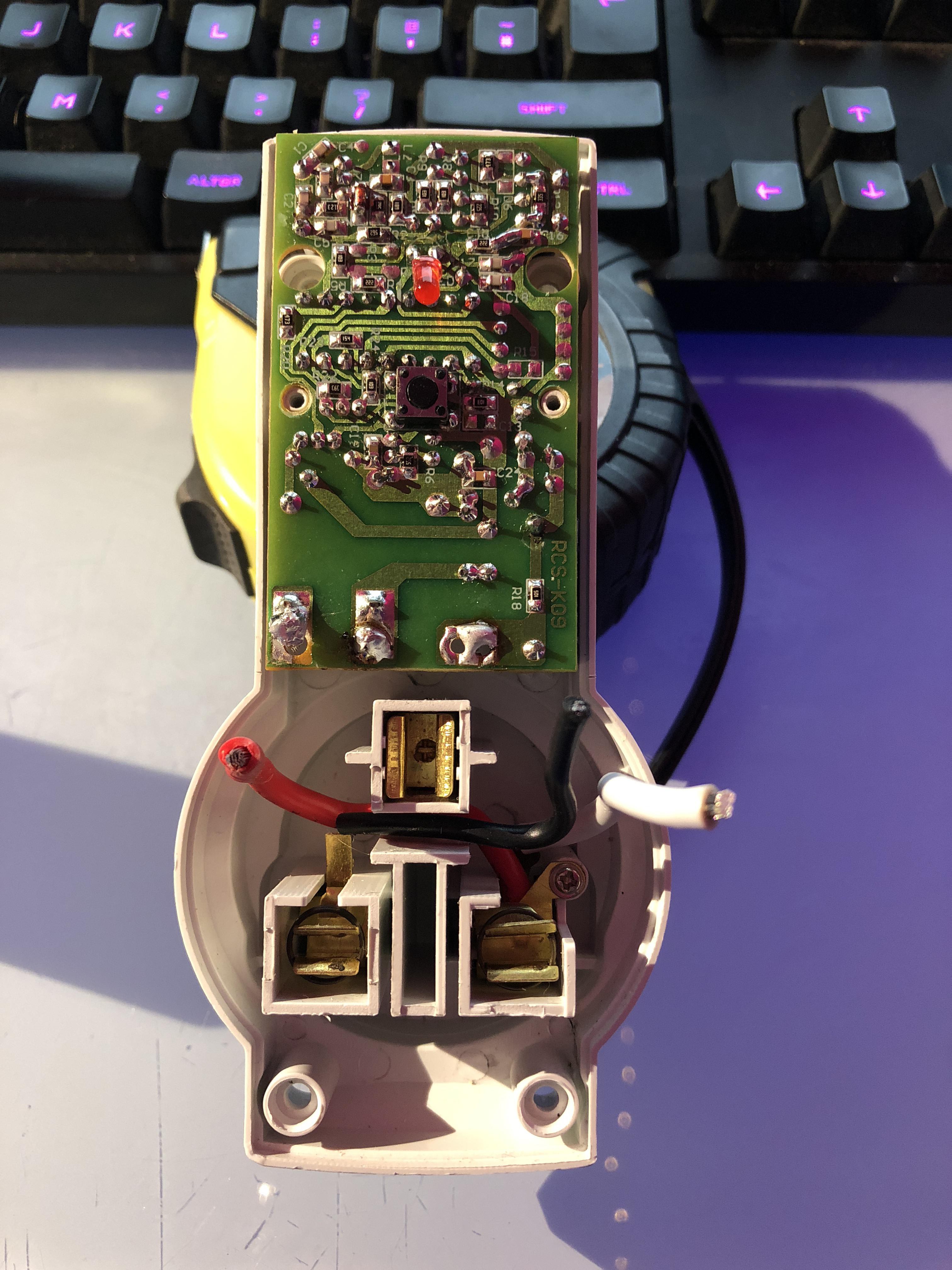
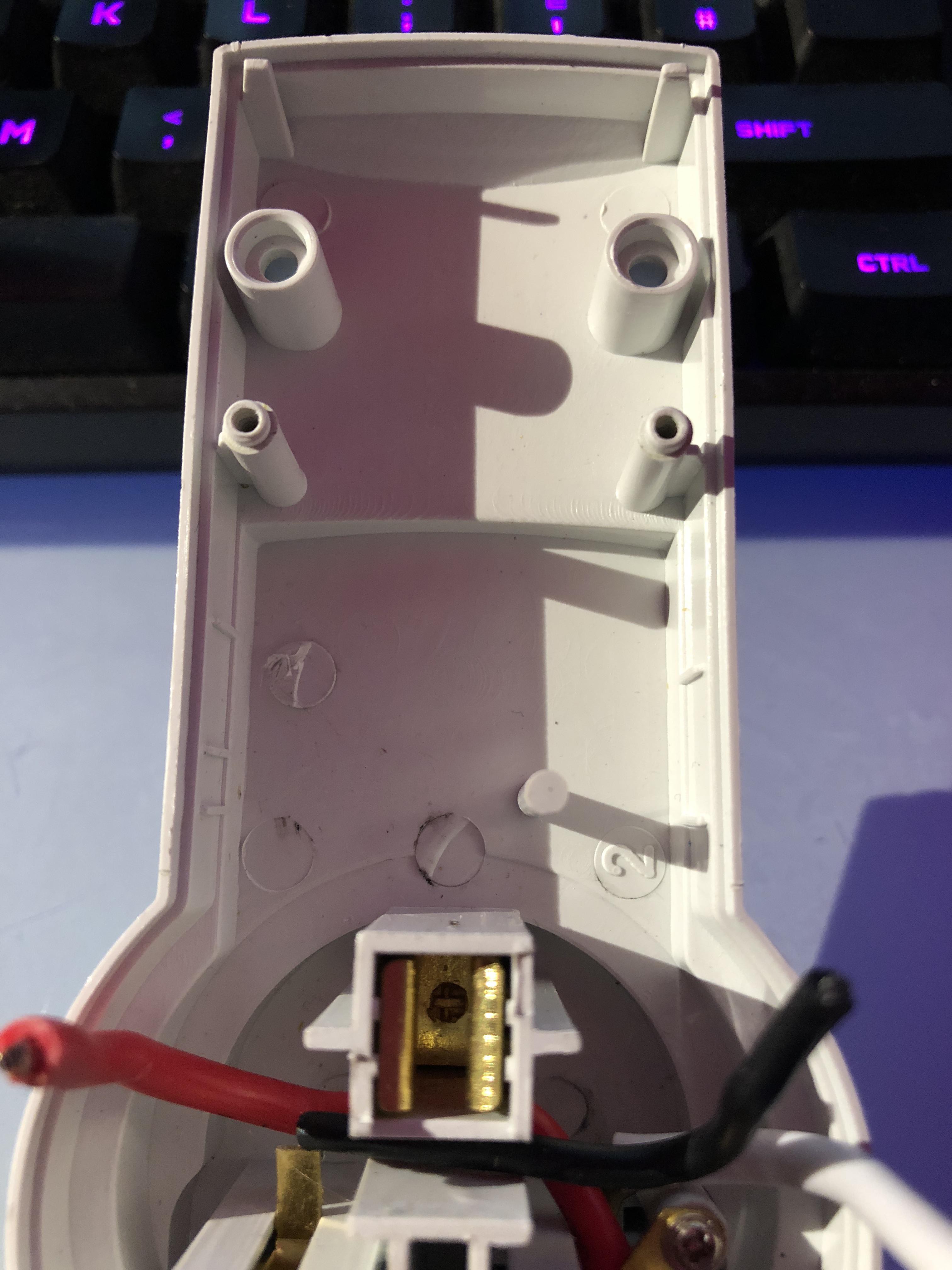
Here's what we have to work with:


There's a bit of depth to work with underneath the board - just under 17mm at the bottom end, tapering off to around 13mm. The board itself is 37x65mm. There are two standoffs for securing the board in the middle, and two holes at the top for the standoffs for securing the other half of the enclosure. There's also one more support standoff underneath at the bottom of the board near the AC terminals to support the board. These restrictions will make placing some of the taller components quite tricky!

In the next update I'll start with the part selection.
 Andy Smith
Discussions
Become a Hackaday.io Member
Create an account to leave a comment. Already have an account? Log In.