PCB is finished, last time features where added :
- Power using only USB (obviously the amplifier will not work)
- Voltage measure of the external power supply thank to an ADC input on the touch screen controller
- Added test points with power supply to easily replace the LCD module
Speaking of test point here is the back side of the PCB :
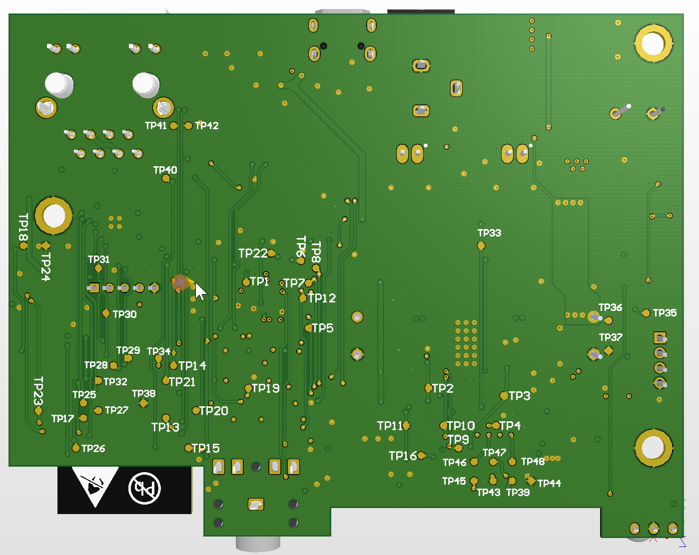
The question is do I leave the test point denominator or do I replace them with signal names ? It could be problematic as the names will take a bigger area...
I need to clean the PCB and generate fabrication files. I'll try to publish files on github in the next few days.
After that documentation...
Discussions
Become a Hackaday.io Member
Create an account to leave a comment. Already have an account? Log In.