Ted Yapo
-
Coin Cell Discharge Tests
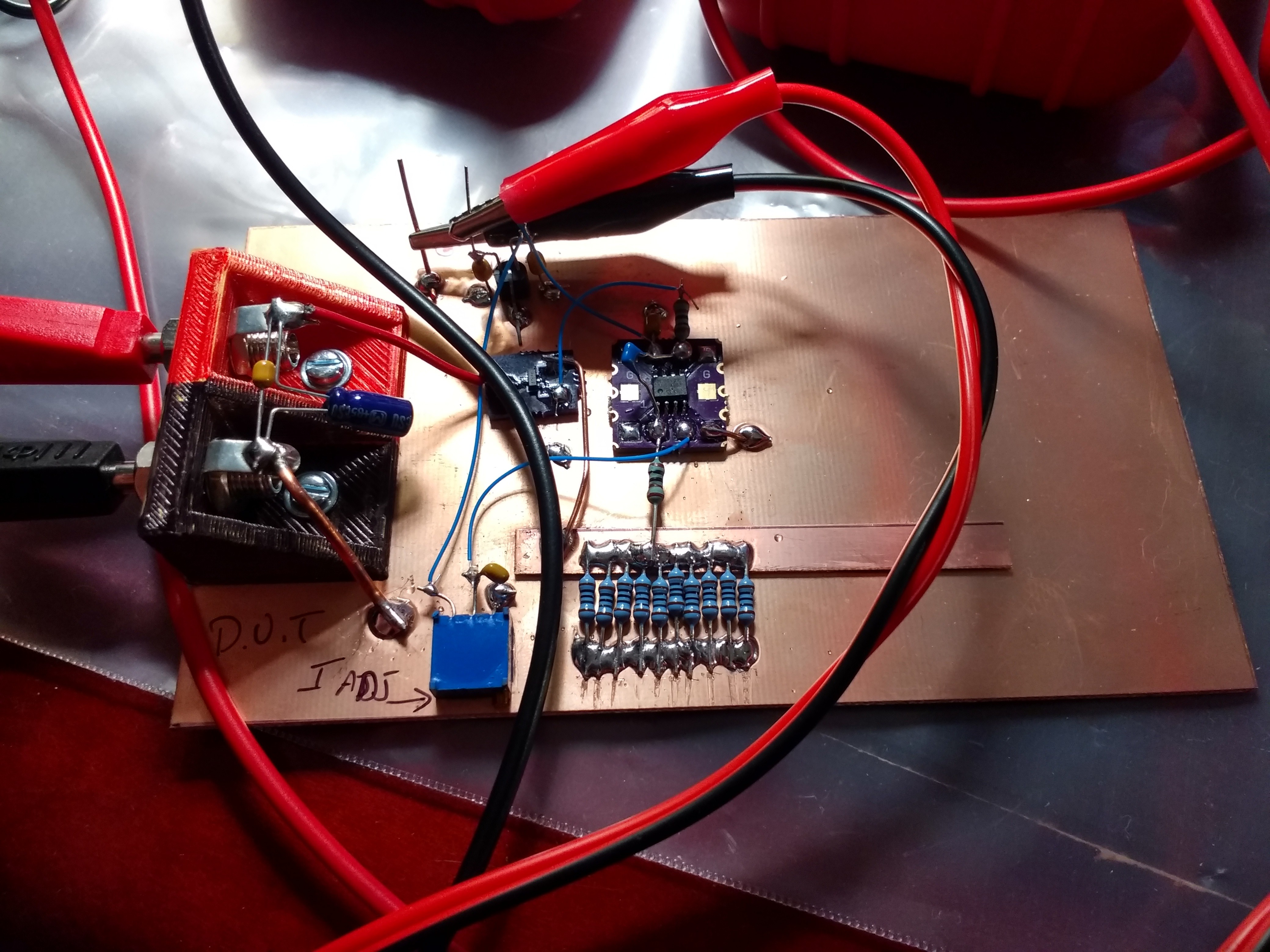
12/14/2017 at 23:26 • 12 commentsEarly on I figured I'd need to test some CR2477 cells to see how much energy they could practically supply in a short time. I finally got around to building the tester and putting it to work (not to spoil the surprise, but things don't look great so far). Here's the tester:
![]()
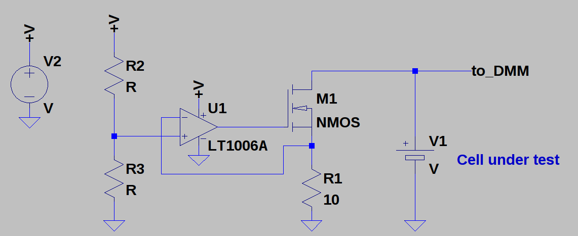
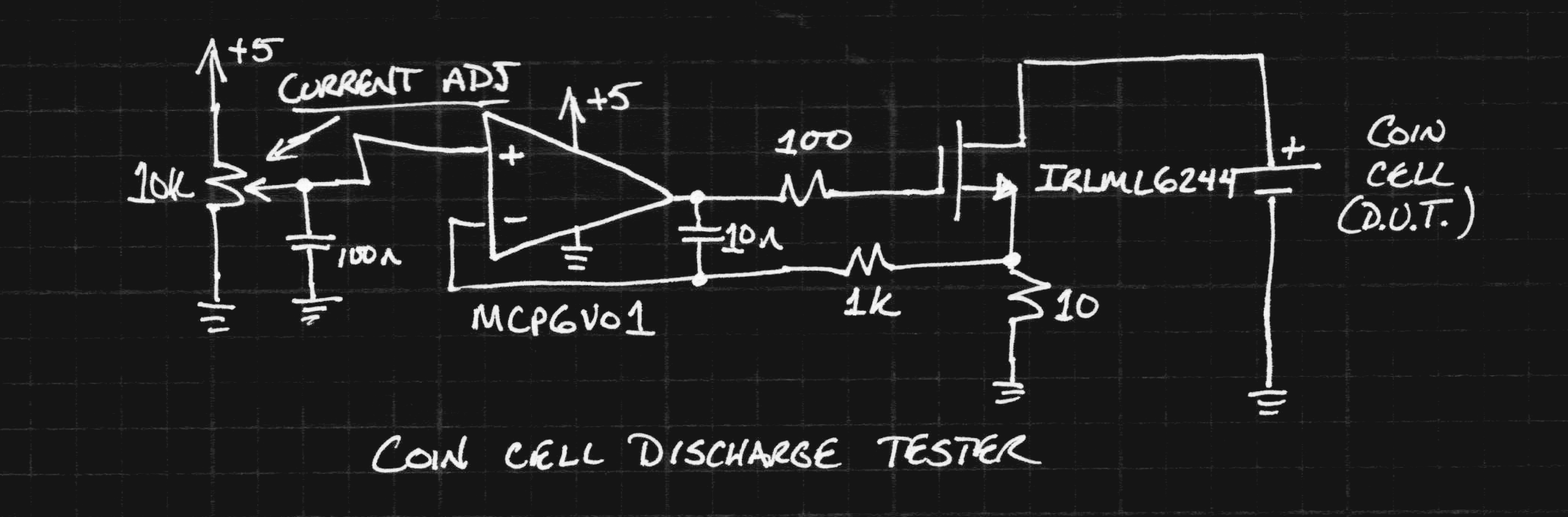
The circuit is basically what I described in an earlier log, except with a few R's and a C added for stability.
![]()
The first low-offset op-amp I found in the parts bin was an MCP6V01 chopper. It's overkill for this application but contributes a ridiculously small error to the result. The cell is discharged at a constant current set by the potentiometer, while serial-port-enabled DMMs log the current and cell voltage (not shown). I didn't have any 1% 10-ohm resistors with a decent power rating, so I paralleled 10x 100-ohms. The MOSFET and op-amp are mounted on #Ugly SMD Adapters.
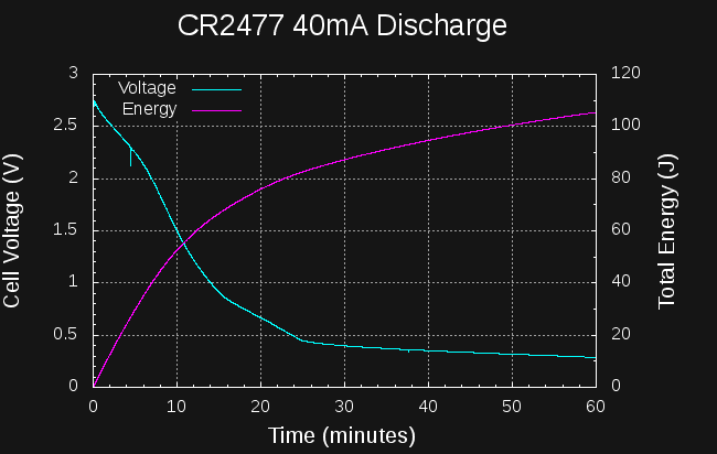
My initial plan was to discharge the CR2477 at a constant 40mA. This represents a C/25 discharge rate, which is completely reasonable for any battery other than a coin cell. For the CR2477, it turns out, this is an enormous drain that wastes most of the energy in the cell. Here is a plot of the voltage during the 40mA discharge as well as the total energy (in this case dissipated as heat in the 10-ohm resistor):
![]()
After 10 minutes of discharge, the cell voltage has decreased below 1.5V, which I think is as low as I can reasonably expect to go using a PIC12LF1571 in the DC-DC converter (the PIC is specified down to 1.8, but I will push it). At the 10-minute mark, the energy extracted from the cell is around 55J. Terrible. Integrating the current to this point yields 6.6 mAh, which is 0.66% of the cells capacity. Awful.
I let the drain continue for about 9 hours, even though after 25 minutes, the cell voltage dropped below the 400mV required to maintain a 40mA discharge in the load resistor. At the end, 157J had been extracted. Ghastly.
Lesson: don't discharge CR2477 cells at 40mA.
What about 20 mA?
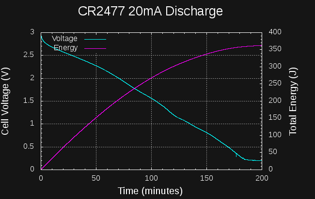
Undaunted, I discharged a CR2477 cell at 20mA (note the different time scale).
![]()
In this case, around 260J and 35 mAh have been extracted from the cell before the voltage drops below 1.5V (lousy). This 5x as much as the 40 mA discharge, but still represents a small fraction (3.5%) of the capacity of the cell. Atrocious. When I finally stopped this test after about 8 hours, 392 J had been extracted from the cell. Dreadful.
Lesson: don't discharge CR2477 cells at 20mA.
Are you seeing the pattern yet? Lower currents will be required to extract more energy from the cell. Of course, these discharge curves don't come anywhere near the 25-hour estimate I originally used for charging (the 20mA discharge is essentially done in 3 hours). Still, the total amount of energy I have been able to obtain from the cells is very low. Abysmal.
What I Got Wrong
So, in my initial estimates of current drain, I assumed that a 1000mAh CR2477 was like a 225mAh CR2032 scaled up by 4x, so I could draw 4x the current (I found data fro CR2032s on the web). The differences between the cells are more subtle than that. The maximum current you can draw is proportional to the electrode area, and assuming the electrode size is proportional to the cell diameter, a CR2477 only has 24^2/20^2 = 1.44x the electrode area. The total amount of reactive chemicals inside may be 4x, but the maximum current you can reasonably draw is likely to be around 1.4x.
I also based my initial estimates on numbers in this article, which says you can use 88% of the available energy in a CR2032 when draining it at 10 mA. Unless CR2032s are much better at higher currents than CR2477s, I just don't see it. I should test a CR2032 for comparison.
What's Next?
There is a trade-off between the length of time taken to drain the cell and the self-discharge of the supercapacitors. The longer you take to drain the cell, the more energy you get, while the more you lose due to self-discharge in the cap. Somewhere in-between, there is a maximum amount of energy you can get into the capacitor.
I'm currently running two more tests. First, discharging a CR2477 cell at 10mA. So far, this is looking better, already having extracted 845 J in about 10 hours, and the voltage is still about 1.5V.
The second test is to get a better estimate of the self-discharge of the 400F supercapacitors. I charged one to 2.33V, and am logging the voltage as it self-discharges. At first, the selft-discharge was around 5.5mA, which is absolutely terrible, but it is dropping steadily now. This is probably due to some of the charge being a surface or shallow charge in the capacitor.
Data from these tests should give an indication of the optimum duration for charging the capacitor from the cell, and how much energy can be expected.
Bootstrapping the PIC
One more idea occurs to me. It seems that under "heavy" drains like these, there can still be a significant amount of energy left in the cell even when the voltage drops to 1.5V or lower. So, why not have the PIC bootstrap its own power supply? Once the supercapacitor is charged to more than the cell voltage, the PIC can be run from the output voltage (a pair of BAT54 Schottky diodes can switch the PICs Vdd). A low-quiescent regulator might be necessary, but the scheme should work, and will allow more energy to be drained from the cell.
Bootstrapping also gives me an idea for running TritiLEDs from single AA cells (lithium or otherwise)...
-
How much current does it really take?
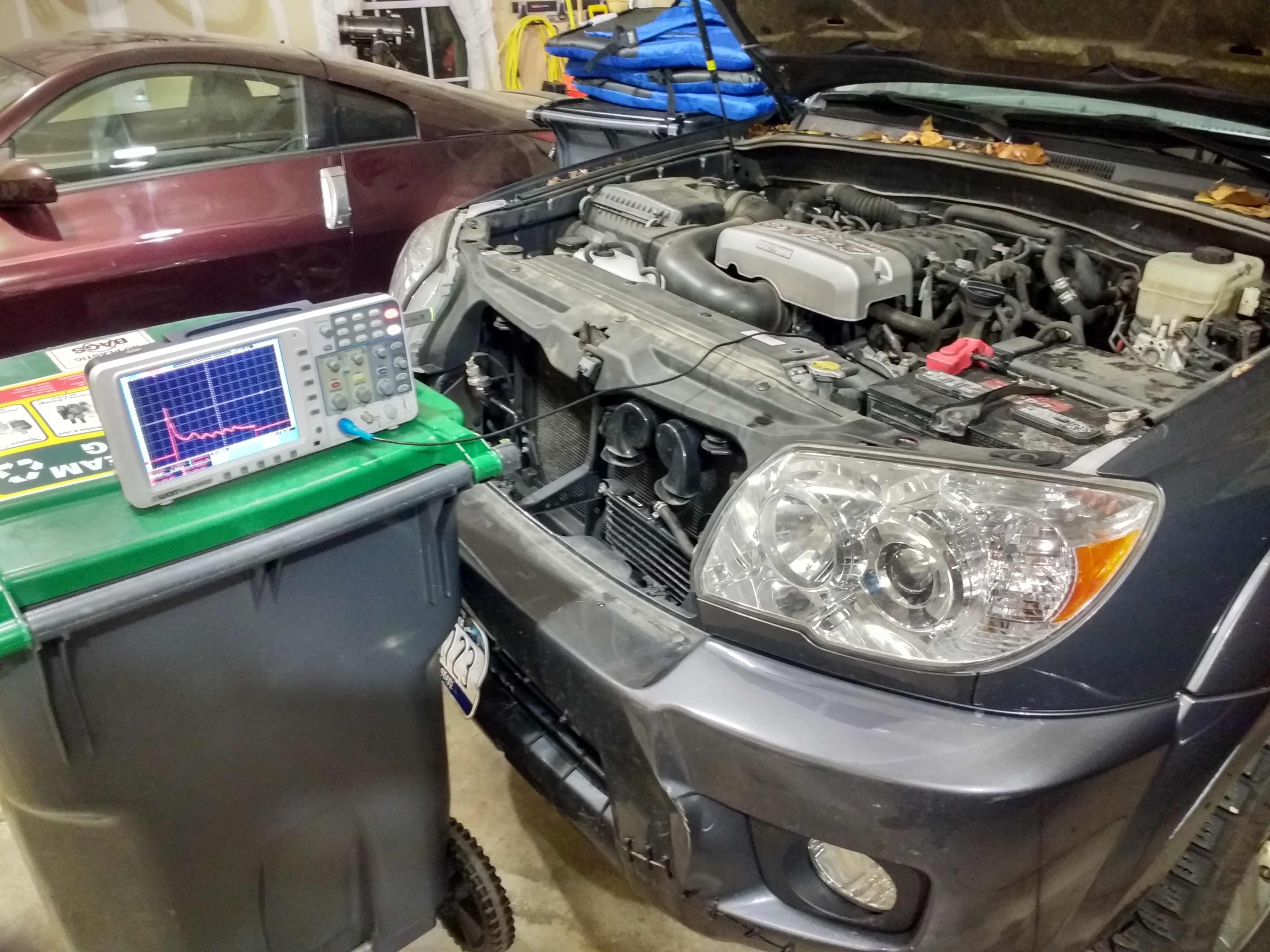
12/13/2017 at 01:44 • 2 commentsI took some measurements on my car today. I hooked the 650A current clamp to an oscilloscope and measured the battery current during starting.
![]()
The engine is a 4.7l V8, which was relatively cold, only having been started a few times briefly before I got the scope triggering right. (You can also see how I fixed my cracked fender with a drill and zip ties at the bottom right).
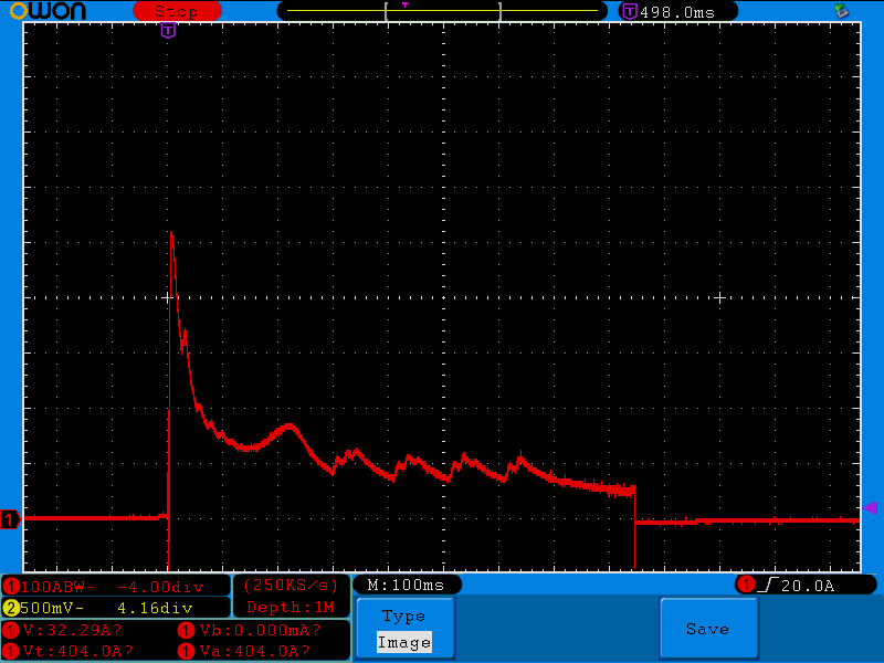
The battery current looks like this:
![]()
The current peaks at just above 500A for about 20ms, then drops below 200A within 50ms. It stays around 150A until about 300ms into the start, then drops to about 100A for the remaining 500ms. The total start time is around 850ms. This doesn't seem too bad.
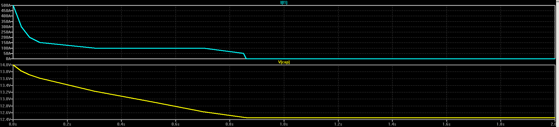
To simulate what this discharge current would do to the capacitor voltage, I made a quick LTspice simulation using a piecewise-linear current source to model the starter current. I assume the capacitor starts at 14V.
![]()
The simulation shows how the capacitor voltage would drop if the starter drew the same current:
![]()
In this simulation, the capacitor voltage ends at 12.4V, so (12.4^2/14^2) = 78% of the energy remains in the capacitor. This is very interesting.
Of course, the current profile will probably look different with the capacitor in place of the battery, but this data is encouraging. It doesn't really take that much energy to start a car. In this simulation, it only took around 1500 J.
-
Help: ideas wanted
12/12/2017 at 17:09 • 16 commentsUPDATE 2017-12-21
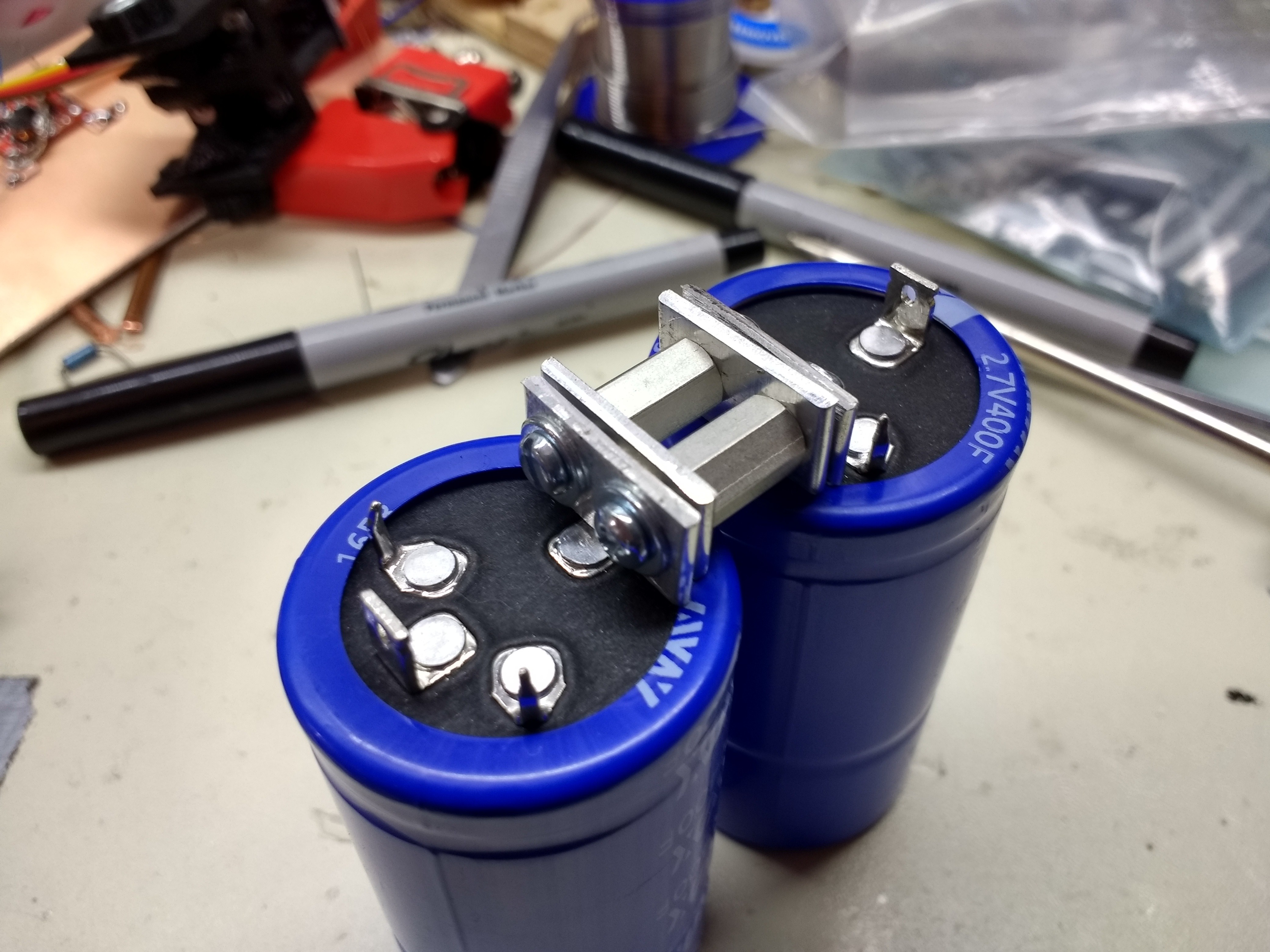
Thanks to everyone for the very helpful suggestions! I've settled on a solution, shown here:
![]()
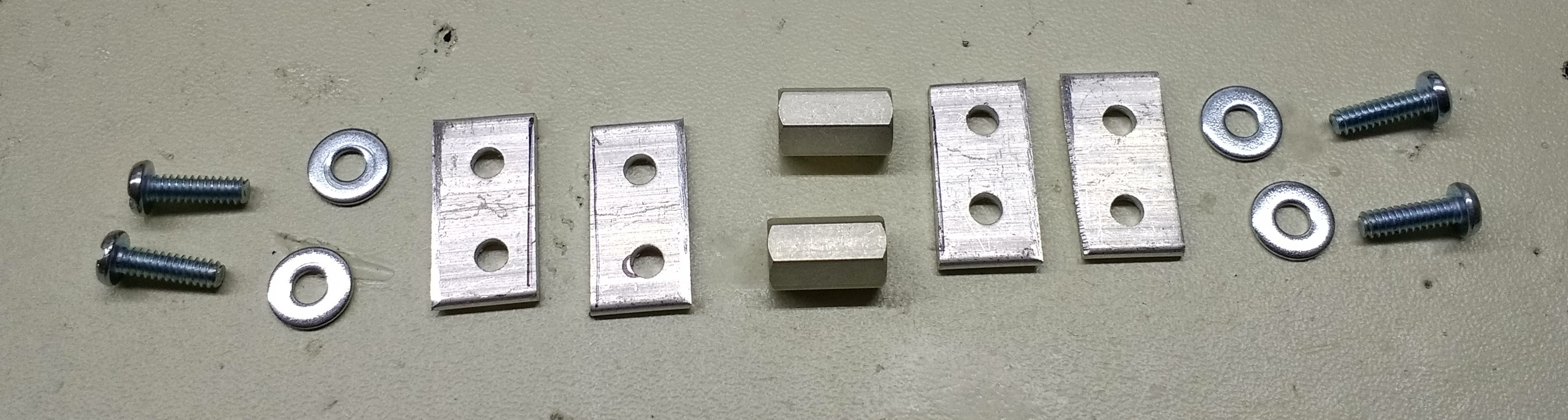
The assembly consists of two threaded hex spacers, four screws, four washers, and four custom 1.5mm aluminum bars I punched and cut to size:![]() It should provide a low-resistance connection, and might not melt :-)
It should provide a low-resistance connection, and might not melt :-)I need to come up with a good way to connect the capacitors in series with a low-resistance connection. I've gone round and round in my head, and haven't come up with the right way yet, so I figured I'd ask you, dear readers, for your input before I just slap something together.
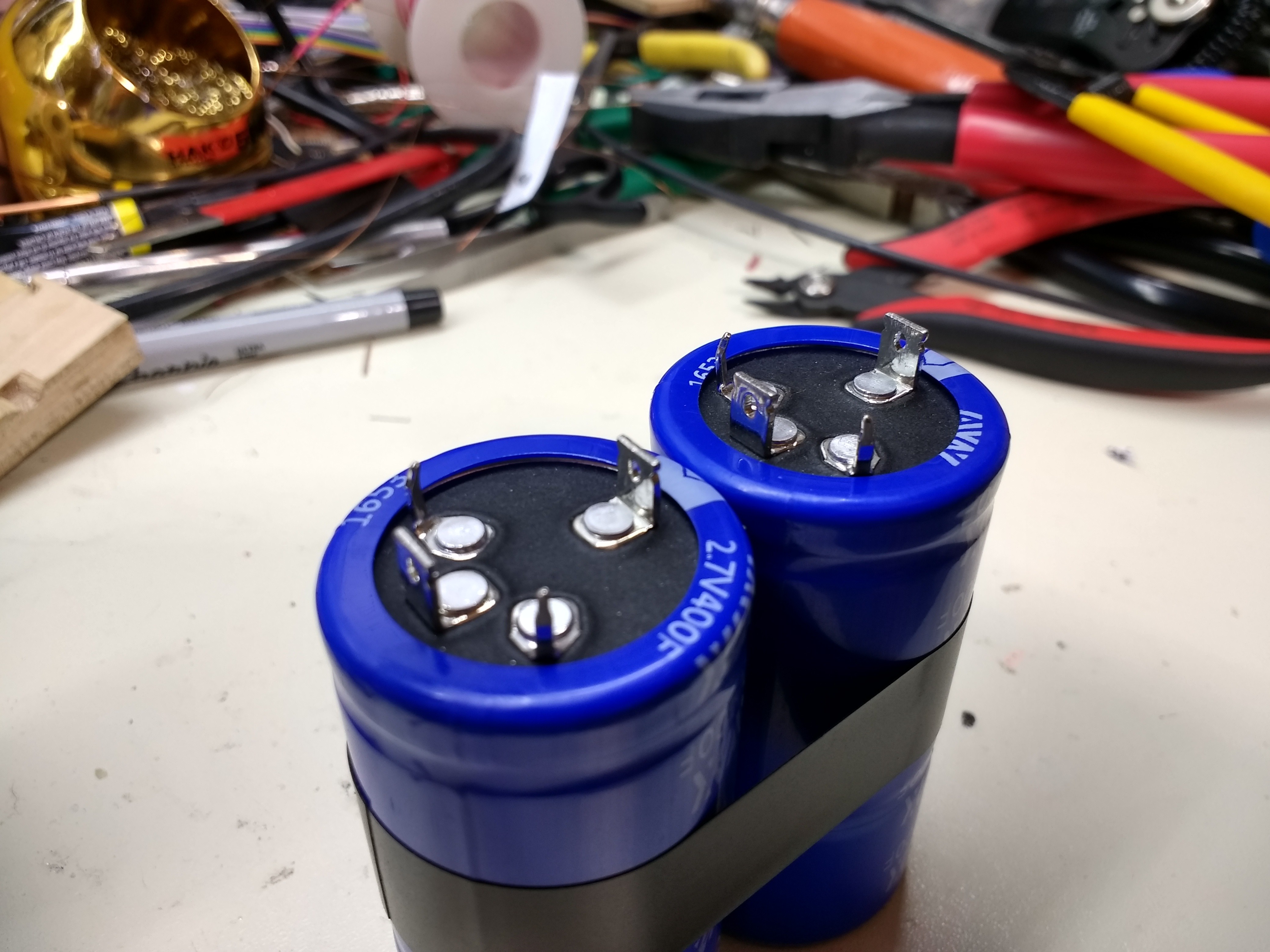
![]()
Here is a picture of two of the capacitors as they will be wired. There are three positive terminals and one negative on each capacitor. The "outside" positive terminals (smaller pins) seem to be there just for mounting reinforcement, so I'm going to ignore those and only connect the rectangular tabs. The tabs are 5mm wide by 6mm long by 1mm thick. Coincidentally, 0.2" Faston connectors seem to fit, but they aren't suitable for the large currents involved.
So, I need to come up with a way to connect those two terminals. I have thought of machining a copper bar with slots to fit the tabs then soldering, or cutting short pieces of solid copper ground wire to fit in-between them, but no ideas so far feel right.
Ideally I'd like a secure mechanical connection first, then add solder to that.
Ideas?
-
Supercapacitor Testing
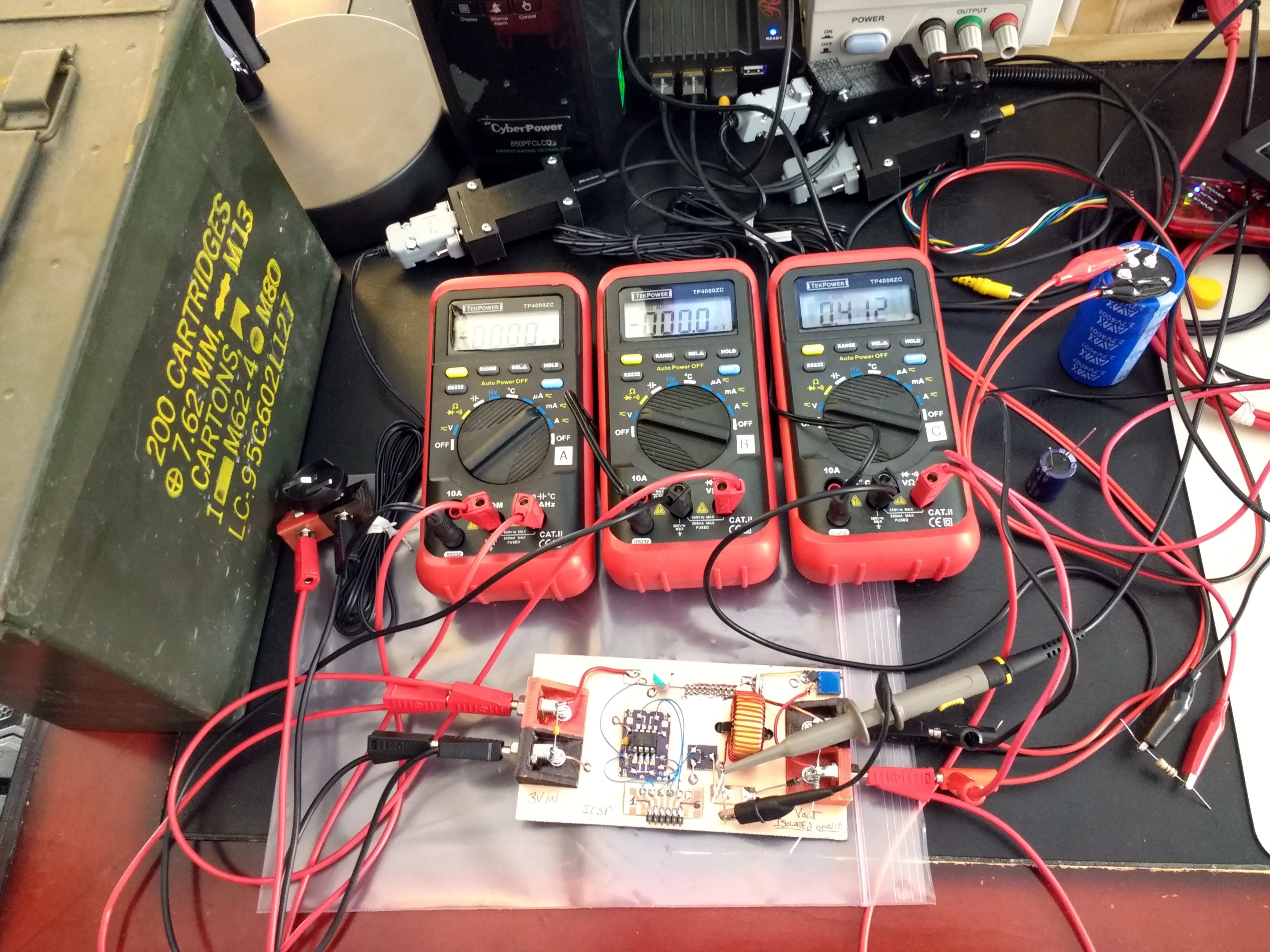
12/10/2017 at 19:13 • 0 commentsMy supercapacitors arrived yesterday, and I've had a chance to do some tests with them. I set up a test rig where I can log data while charging the caps. I don't have the charge balance boards back from OSH Park yet, so I've been testing a single capacitor.
![]()
The test setup includes three serial-port-enabled DMMs and a steel ammo can to contain the coin cell just in case it bursts during high-rate discharge.
Here's an interesting bit of trivia: a CR2477 coin cell is rated to deliver 10,800 J of energy. The 7.62mm NATO rounds originally stored in the ammo can have a muzzle energy of 3,304 J, so the coin cell can deliver as much energy as three .30-caliber rifle bullets. Just much less quickly.
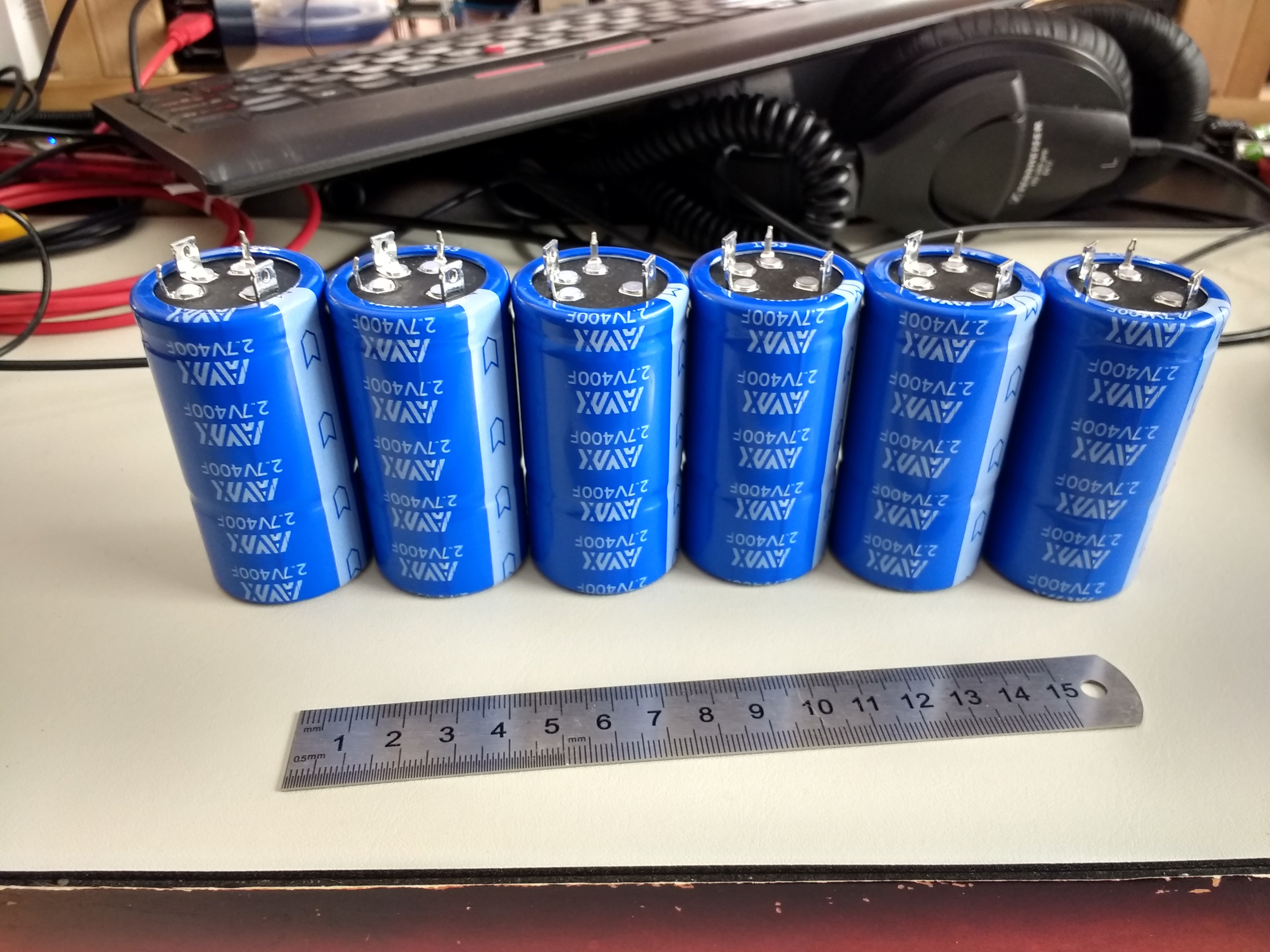
Here are six of the capacitors, 400F each:
![]()
I bought eight of them, figuring that a few extra to play around with could be fun :-) I'll probably wire them together in this in-line arrangement, which will place the output terminals close to where they would be on a car battery; this will make it easier to connect the car's battery cables to the capacitor pack. I might print a case for them just for fun.
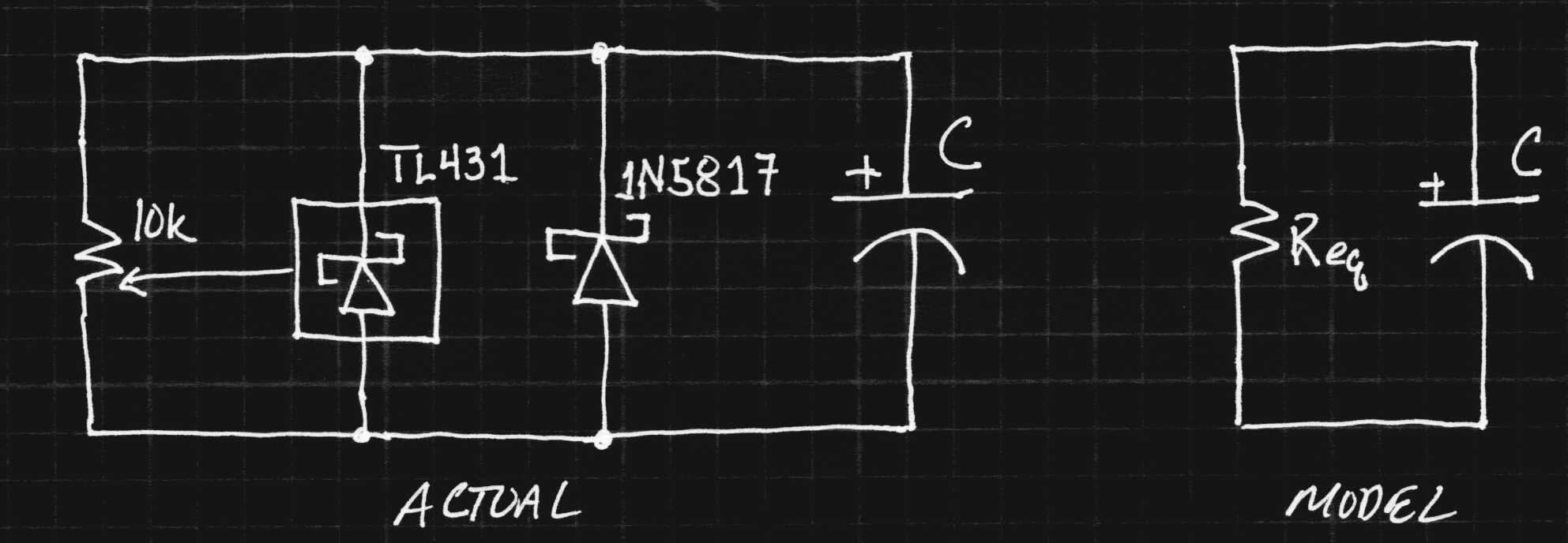
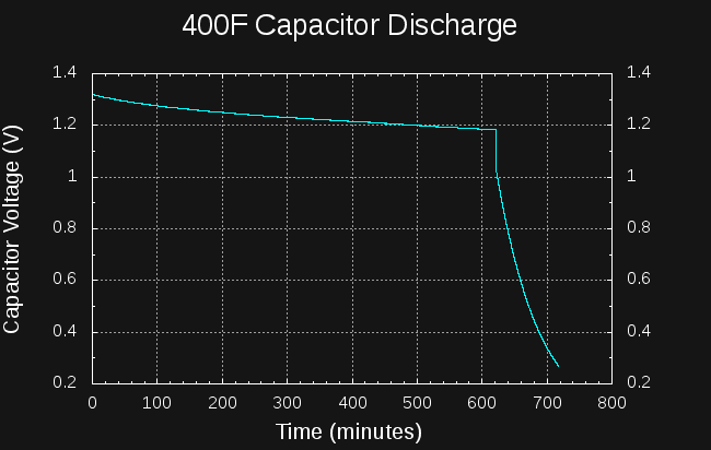
I arranged a simple test overnight to measure the capacitance and self-discharge rate of a single capacitor. I charged the capacitor for a while, then logged data while it "self" discharged. This discharge was due to a combination of true self-discharge, leakage through the 1N5817 diode, and the over-voltage protection circuit, which is a 10k trimmer and a TL431 shunt regulator. As a fist approach, I've chosen to model all the leakage as a parallel R, treating the whole thing as a single RC circuit.
![]()
If I knew the actual value of the capacitance, I could determine Req from the discharge curve. So, in order to find both the Req and capacitance value, C, I added an extra 10-ohm resistor across the capacitor and continued to log the voltage. The result is a pair of exponential curves:
![]()
For each curve, I estimated the RC time constant by linear regression; To do this, you can re-arrange the equation:
to get:
which is easily recognized as the form (y = a x + b), so can be fit with linear regression.
For the first part of the curve, this yields an estimate of 330,914 for the RC time constant. For the second part (with the 10-ohm resistor added in parallel), the RC time constant is now much lower, 4298. Combining these two measurements allows us to determine Req and C, since we have two equations for the two unknowns:
Solving these equations simultaneously (I used maxima) yields C = 435F, and R = 760 ohms.
The capacitance seems reasonable for a 400F -10/+30% part, but the equivalent resistance seems low - this would mean a leakage current of 3.5 mA at a fully-charged 2.7V. The capacitor itself has a maximum 1mA leakage, the Schottky diode 1mA (at 20V reverse voltage, so it should be lower here), and the potentiometer and regulator should be only a few tens of uA maximum. Looking at it another way, with RC=4298, the capacitor will lose 10% of its energy in 3.7 hours, or half of its energy in 25 hours.
I will measure the leakage current of the TL431 and Schottky diode separately, and see what those look like.
This isn't necessarily terrible news, though, since I don't intend to leave the capacitors connected across the charger when it isn't running. Now, I need to re-do this experiment without the charger connected to get a better estimate of the self-discharge of the capacitor alone.
EDIT: some of the "extra leakage" I detected is probably due to dielectric absorption issues. I see the datasheet specifies 1mA maximum leakage after 72 hours - I interpret this to mean the capacitor is "soaked" at the maximum voltage for 72 hours to ensure fully saturating all the theoretical little RC's inside before testing leakage. I do notice that there's a quick "step change" in capacitor voltage when first applying a charge or load - probably reflecting a shallow charging or discharging. I can probably avoid most of the self-discharge issues by arranging the engine starting test to happen right at the end of charging.
-
Bad capacitors lead to bad measurements: now 62% efficient
12/09/2017 at 02:40 • 0 commentsMy initial estimate of 33% efficiency was due to a bad supercapacitor from the junk box. I still haven't fully diagnosed the problem with that capacitor (high ESR might be part of the issue), but measurements with a new, verified, one look much better.
![]()
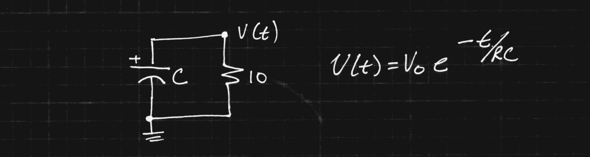
The 400F capacitors won't arrive until Monday, so I did some new measurements with a 10F/2.5V aerogel capacitor that I bought some years ago (it is now obsolete). Despite its age, it was still in the sealed DigiKey bag in my parts bin. To check its capacitance, I charged it to 2.0V, then timed how long it took to discharge to 1.0V when loaded with a 10 ohm resistor: 73 seconds. The voltage follows an exponential curve:
Using this equation, you can solve for C. It's a fun little exercise; I did it in 8 lines on a scrap of paper, but this maxima code will do the same thing faster:
solve(V[t] = V[0] * exp(-t/(R*C)), C);Either way, you get the following:
Using this formula, we calculate a capacitance of 10.5F. Not bad for a -20/+80 tolerance part.
New Efficiency Estimate
So, armed with a validated capacitor, I timed how long it took to charge this new capacitor to 1V from a CR2477 cell with the converter. The converter was drawing around 34mA for 82 seconds. I will assume the battery voltage was 3V, because I didn't measure it (more about this below). This equals 8.4J out of the battery. Charged to 1V, the capacitor holds 5.25J, so the transfer was 62.5% efficient. This is much closer to what I would have expected.
So, there's a subtlety involved here, because under load the battery voltage is less than 3.0V. I've chosen to use the nominal 3.0V in the efficiency calculation because this will approximately account for losses due to internal resistance in the cell: the energy actually delivered by the cell is somewhat less, but this should give a rough approximation of the capacity of the battery that has been consumed. The 62.5% number is closer to an end-to-end efficiency measurement rather than just the converter itself.
So far, I haven't connected enough DMMs to monitor the cell voltage and current at the same time. I have three serial-port-enabled DMMs that I'll connect up once I clear some space on the workbench so I can log data during the entire charging process (cell voltage, cell current, and capacitor voltage).
Next Steps
So, the efficiency at low output voltages looks reasonable now. I'd still like to improve it, and will be looking more closely at where the losses are. But, losses are likely to increase when stepping up to higher voltages (like the 14V required on the big caps). So, until the final caps arrive, I'll find the largest capacitance I can that's rated for 16V or more, and time some higher-voltage charges.
Although the caps are still in transit, my 650A current probe did arrive (thanks, Amazon), so I can check out the voltage/current curves when starting my car (with the normal battery - for now).
-
First Prototype DC-DC Converter
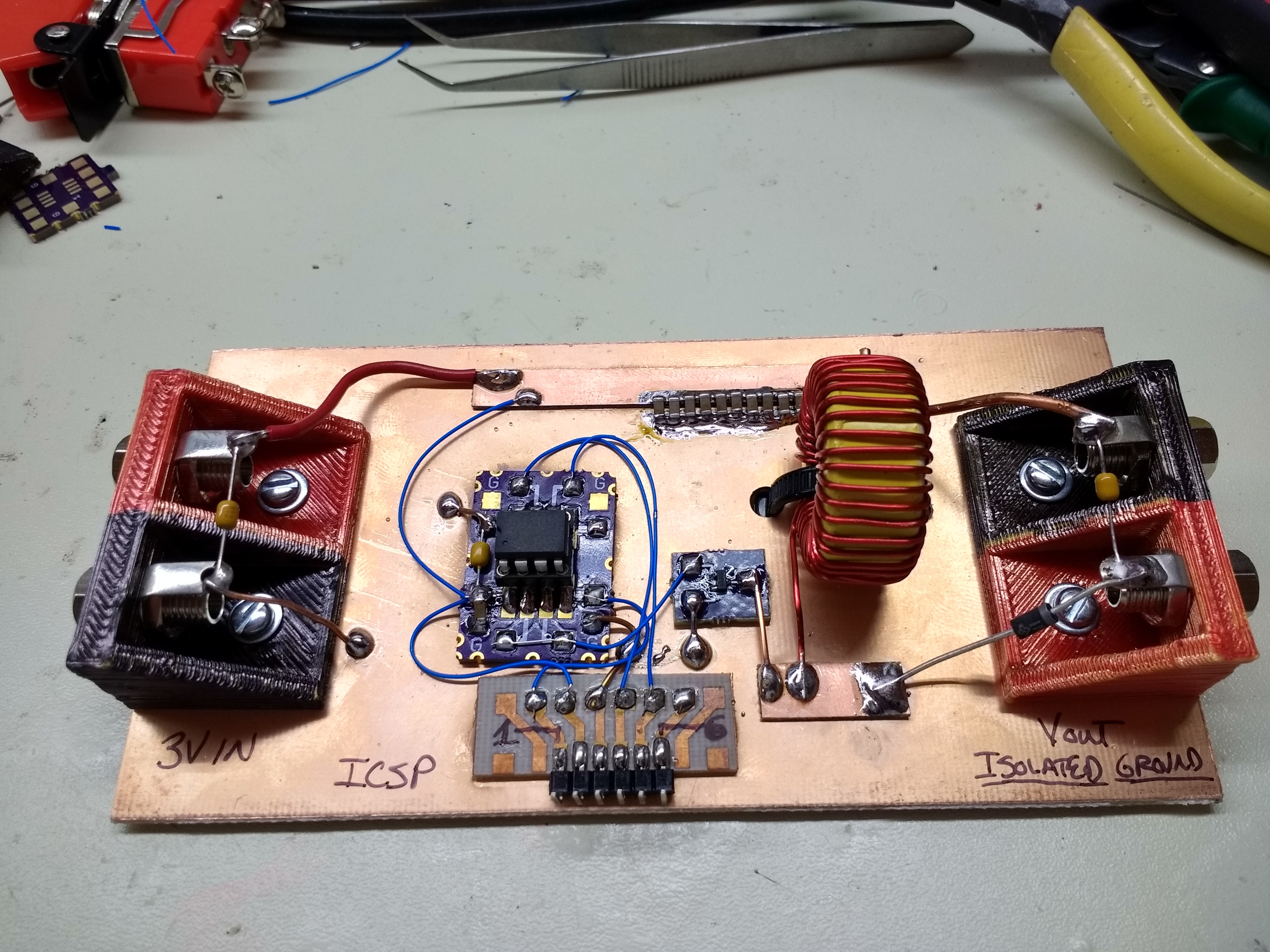
12/07/2017 at 15:10 • 9 commentsI wired up a first prototype converter last night and coded up a quick test this morning. So far, it "works," but not great.
![]()
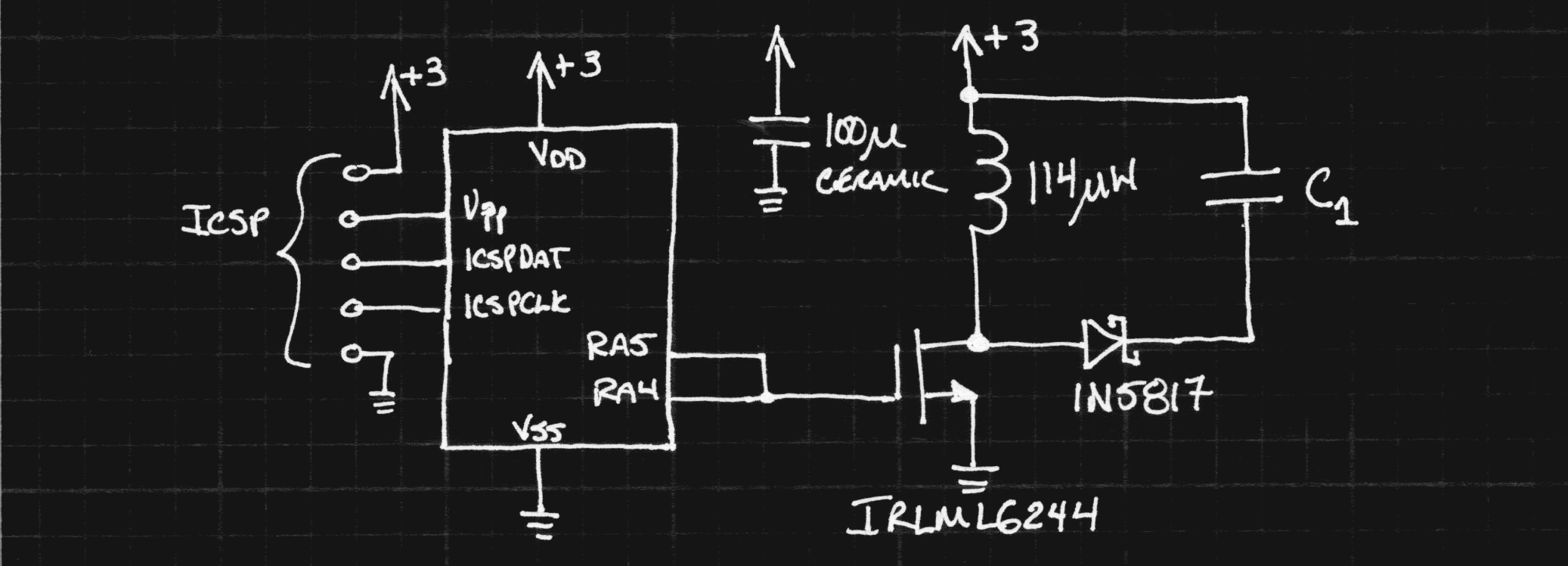
The converter is based around a PIC12LF1571 that drives a simple MOSFET/inductor/diode circuit. Here's the schematic:
![]()
The PIC code (attached at the end of this log) generates a 17us pulse every 94us to magnetize the inductor by switching on the MOSFET. When the magnetic field decays in the coil, the voltage rises to maintain the same current flow, charging C1 through the Schottky diode.
I chose this topology because I had better NMOS transistors in stock than PMOS. I first saw the IRLML6244 when @Elliot Williams used it in his version of #TritiLED, and it has quickly become one of my go-to parts. I might end up substituting something else later, but for now, this seems fine. Two output pins from the PIC are paralleled to increase the drive current and promote faster switching in the FET.
I originally modeled the circuit with a BAT54 diode, because everyone has a million of them, but the 1N5817 is more efficient in this circuit due to the large current pulses. The downside to the 1N5817 is the larger reverse leakage (up to 500uA, even 1mA at 20V on some datasheets). Quick estimates make it more efficient, but I'll have to examine this in more detail.
I wanted a low-ESR capacitor, and the best I could come up with was 10x 10uF 1206 ceramic caps in parallel. I'll probably add another few hundred uF of low-ESR polymer caps when I find the missing bag of them around here. This large capacitance averages out the current drawn from the cell so that it doesn't see the hundreds of mA drawn by the inductor during the pulses. There are some other miscellaneous bypass caps on the board, but they probably don't do anything interesting :-)
I didn't have any beefy inductors of around 100uH in the junk box, so I hand-wound one on a core salvaged from an old power supply. Nearest I can figure, the core is a T131-26 (yellow/white paint). I wound 35 turns of 20AWG wire on there, which ends up measuring out to 115uH, as predicted by the formulas (113.9).
I've only had a chance to test the converter briefly, and so far it "works," charging a 10F capacitor to 1V in a little less than 2 minutes, while drawing 43mA from a CR2032. A quick calculation shows that this is 15.5J out of the cell, with 5J stored in the capacitor for an efficiency of around 33%. I need to at least double that to hit my goal of 67F charged to 14V. In the circuit's defense, I didn't precisely time the charging, so the measurement might be off. Another possibility is that my 10F capacitor is more than 10F. It came from the junk box, and isn't marked with a tolerance, so who knows.
Next, I need to instrument the circuit to see what's going on - I'll add a 0.1-ohm resistor in series with the inductor so I can see the current waveforms, which will probably be the most interesting.
I also need to add an over-voltage crowbar to the output. With the 67F capacitor, there probably won't be any danger of over-charging, but the smaller capacitors I have to play with for now could easily be damaged by a few minutes of inattention. My plan is to add an adjustable shunt regulator, a TL431, directly across the output. The power output of the converter is low enough so that the TL431 can just dissipate it all once the target voltage has been reached.
Here's the trivial code running on the PIC:
;;; ;;; coin_cell_cap_charger.asm: DC-DC converter for charging supercapacitors ;;; from coin cells ;;; ;;; Copyright (C) 2017 Theodore C. Yapo ;;; Licensed under MIT license (see file) ;;; LIST P=12LF1571 #include <p12lf1571.inc> ERRORLEVEL -302 ERRORLEVEL -305 ;;; ;;; I/O pin configuration ;;; GATE_DRIVE_A equ 4 GATE_DRIVE_B equ 5 __CONFIG _CONFIG1, _FOSC_INTOSC & _WDTE_OFF & _PWRTE_OFF & _MCLRE_OFF & _CP_OFF & _BOREN_OFF & _CLKOUTEN_OFF __CONFIG _CONFIG2, _WRT_OFF & _PLLEN_OFF & _STVREN_OFF & _BORV_HI & _LPBOREN_OFF & _LVP_ON ;;; ;;; variables in Common RAM (accessable from all banks) ;;; CBLOCK 0x70 delay_counter reset_counter ENDC ORG 0 RESET_VEC: movlw .255 movwf reset_counter BANKSEL ANSELA movlw b'00000000' ; all digital I/O movwf ANSELA BANKSEL LATA clrf LATA BANKSEL TRISA ;; set gate driver lines as output movlw ((0xff ^ (1 << GATE_DRIVE_A)) ^ (1 << GATE_DRIVE_B)) movwf TRISA BANKSEL OSCCON movlw b'01101010' ; 4 MHz HF osc movwf OSCCON MAIN_LOOP: BANKSEL LATA movlw (1 << GATE_DRIVE_A) | (1 << GATE_DRIVE_B) movwf LATA ;start inductor ramp-up nop nop nop nop nop nop nop nop nop nop nop nop nop nop nop nop clrf LATA ;end inductor ramp-up movlw .26 call DELAY_3W decfsz reset_counter goto MAIN_LOOP reset ;;; delay 3x value in W (W must be >= 3; minimum 9 cycle delay) DELAY_3W: addlw -.2 movwf delay_counter DELAY_3W_LOOP: decfsz delay_counter bra DELAY_3W_LOOP return ;; fill remainder of program memory with reset instructions fill (reset), 0x0400-$-2 END -
Extracting energy from coin cells (quickly)
12/05/2017 at 02:35 • 0 commentsI need to test some CRxxxx coin cells. So, I'm going to build a tester. Here's the rough idea.
![]()
The actual parts will depend on what I find first in the parts bins. The op amp maintains a constant discharge current from the cell through R1, while the cell voltage is monitored by a serial-port DMM. With this setup, I can measure the discharge characteristics of the cell at various current drains.
Why do I feel the need to do this? The amount of energy you can extract from a cell depends on the rate of discharge: faster discharge means less energy available. This is especially true for coin cells.
Jack Ganssle wrote an interesting article about his experiments with CR2032 cells on embedded.com a while back. I read it before when playing with TritiLEDs but quickly decided that his findings didn't apply to the really low current drain of those devices. I do agree with him that it's pointless to estimate run-times in excess of cell shelf life, though. (Shelf life for CRxxxx cells is generally taken to be 10 years.)
In any case, the article describes the problem with high-drain use of coin cells - the internal resistance increases quickly as capacity is used, and this resistance consumes more and more of the power as the cell ages. One data point from the article is that at a 30mA drain, you can only extract 39% of the energy from a CR2032 cell. This equates to a C/7.5 drain rate (225/30), which is very high.
I'm planning to use CR2477 cells, which have about 4.4x the capacity of CR2032s (1000 mAh vs 225 mAh). My initial thought was to discharge the cell (and charge the capacitors) at C/25 (25 hour rate), which for the CR2477 is 40mA. If we assume a CR2477 is just a 4.4x larger CR2032, then this would be equivalent to around a 9 mA drain on a CR2032. The article has curves from a 10 mA drain on a CR2032, which show that 88% of the energy can be extracted from a CR2032 at this rate before the cell voltage hits 2.0V. So, I roughly estimate that I can extract 88% of the energy from a CR2477 discharging it at a constant 40 mA.What does it all mean? I might be OK with a 25-hour discharge/charge cycle. But, I think I should build a version of the circuit above and test some cells. I'll probably test some CR2032s initially, since they're so much cheaper than CR2477s (and I have a *lot* of CR2032s around for another project :-)
You may be wondering why I don't just charge the capacitors over a week (or more) to extract most of the energy from the cell. Other than having to wait for results (before the contest ends), the other problem is the self-discharge of the supercapacitors. The capacitors specify a maximum leakage of 1mA, which I'd like to keep to a small fraction of the charging current to maintain efficiency. There's probably a cross-over point where the extra capacity extracted from the cell is lost to capacitor leakage.
-
Proper care and feeding of supercapacitors
12/03/2017 at 23:15 • 2 commentsStrings of capacitors have similar issues to strings of lithium ion cells: differences between cells can cause one or more cells in a string to become overcharged. In the case of capacitors, leakage current and capacity differences are the culprits.
![]()
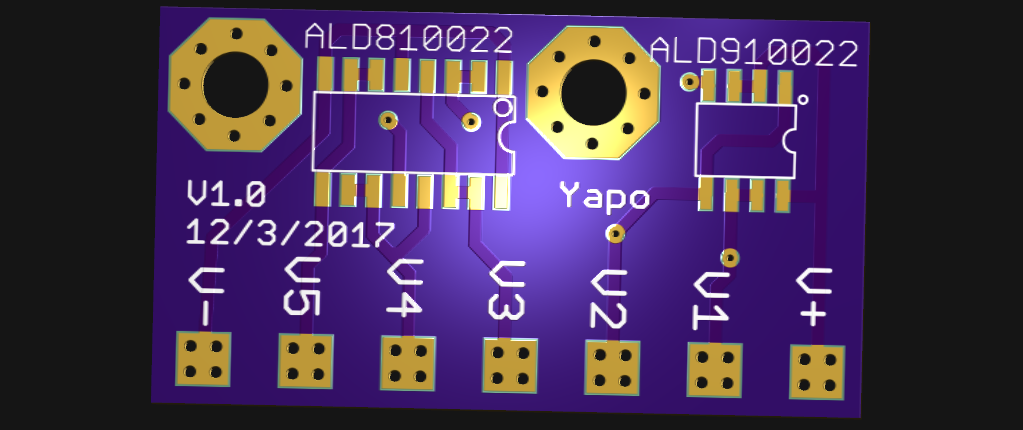
To keep all the capacitors happy, you need a charge balancing circuit, so I designed a PCB around the ALD810022/ALD910022 Supercapacitor Autobalancing MOSFET IC's. These devices are amazingly simple in operation, using V/I curve of specially trimmed MOSFETs to shunt excess charging current around fully-charged capacitors. You simply need to connect the board pads to each node in the capacitor string. The Eagle design files for the PCB are in the GitHub repo.
ALD markets similar boards, which I will diplomatically call "high-margin items". You can get an un-populated PCB from DigiKey for around $20. The PCB above will cost you $5.35 for three copies at OSH Park. Even splurging for Super Swift service, I'm only paying $10.70 for three copies. Not bad.
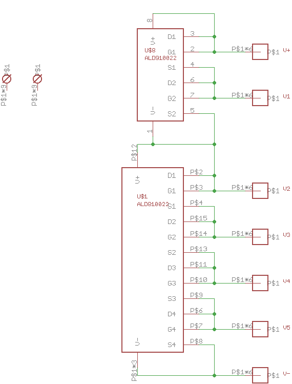
The circuit is pulled right from the datasheet; the 8100 device contains 4 MOSFETs and the 9100 two of them, so both packages neatly handle six capacitors.
![]()
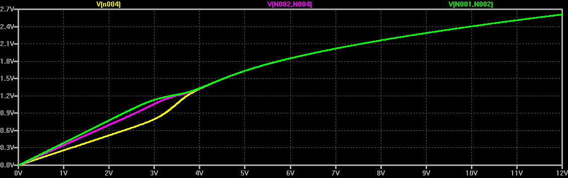
To see how these devices work, I ran a quick LTspice simulation using MOSFETs in the library - of course, these devices don't match the capacitor voltage I'll be using, but the qualitative behavior is similar.
![]()
C1, C2, and C3 represent capacitors with a spread of capacitance and leakage current (modeled with parallel resistors). The three MOSFETs start to shunt current around each capacitor as it reaches about
1.3V. For voltages above 4.0 for the string, the capacitor volatges become balanced, which you can see in this DC sweep:![]()
With the ALD8100xx devices, ALD has accurately trimmed the V/I curve on each MOSFET instead of the random choice of devices I made in this rough simulation. In practice, you choose the version of the ALD ICs based on the maximum leakage current and maximum voltage for your capacitors.
Capacitor Selection
I chose to use a string of 6 SCCY68B407SSBLE capacitors from AVX. These caps are rated 400F at 2.7V, so the string of 6 will have a maximum 16.2V rating with 66.7F of capacitance. To select the proper ALD charge balancing IC's, I note from the datasheet that the capacitors have a maximum leakage current of 1000uA. From the ALD81-9100xx family datasheet, I see that the ALD{8,9}10022 parts have a forward voltage of 2.64V at 1000uA of current, which will keep each capacitor safely under the 2.7V limit. Perfect - DigiKey had them in stock, too. They're on the way.
The capacitors have a maximum ESR of 2.2mOhm, so the string of 6 will have 13.2mOhm resistance, plus whatever wiring I add. They are also specified for a 245A peak discharge current. This is probably enough to start most 4-cylinder engines, and maybe some 6-cylinder, but probably not my daily ride, which has a 4.7l V8. I may have to find another vehicle to experiment with. Then again, the ESR alone will allow currents of around 1000A, so if I use beefy wiring, maybe I can push the caps a little.
Either way, I'll have to make sure the engines are properly warmed up for the attempt(s). Cold oil is tough to get moving.
-
Buck, boost, or bust?
12/03/2017 at 05:00 • 0 commentsAstute readers will have noticed I incorrectly said I needed a boost converter to transfer energy from the 3V coin cell to the 14V capacitor bank.
![]()
This is true once the capacitors are charged above the cell voltage, but from 0 to 3V or so, I need a buck converter. Unfortunately, I can't just connect the coin cell directly to the capacitors to get them initially to 3V. If I did that, the internal resistance of the cell would waste too much power - to get the maximum energy from the cell, it has to be transferred slowly, probably over the course of many hours. So, I need a buck/boost converter.
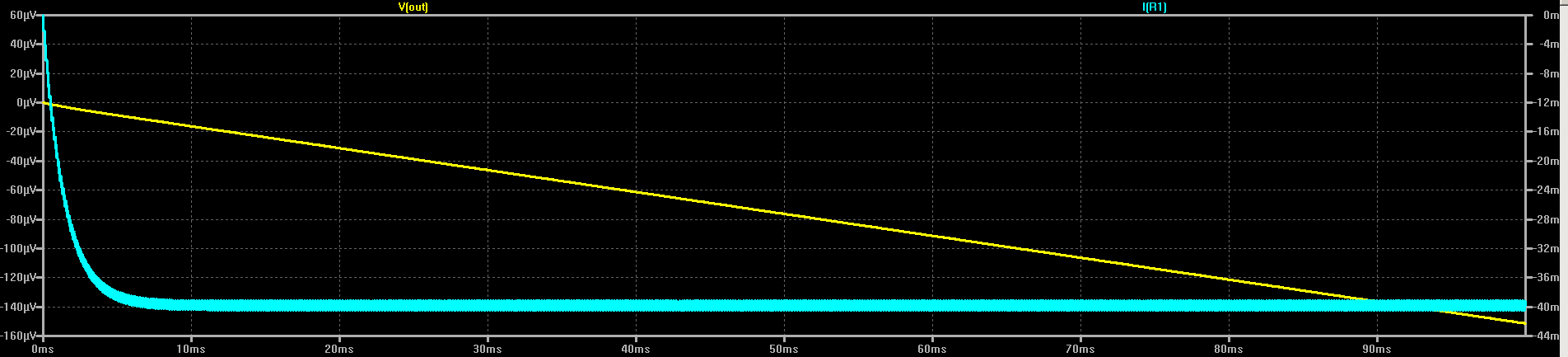
Since I don't really care that the cell and the car share a common ground, I can use the simplest buck/boost topology, which incidentally inverts the output voltage. The car won't mind as long as I get the polarities right at the battery connection. I made a first pass at a LTspice simulation for the converter, as shown above. I chose a P-channel MOSFET from the library basically at random; none of the components are set in stone yet. R1 simulates the internal resistance of the CR2477 cell - this changes over the life of the cell, so I'll have to account for that at some point. C1 serves to smooth the current drain from the cell, providing a reservoir for the current pulses into L1. M1 switches current into the inductor when turned on, then switches off to allow L1 to drain into D1 and C2, the B.F.C. (note the "67" with no units - that's 67 Farads).Here is what the cell current and output capacitor voltage look like in the first 100ms of simulation:
![]()
The circuit draws about 40mA from the cell, which would deplete the cell in roughly 25 hours - I may have to wait a day for the capacitors to charge, but this should extract a decent amount of the available energy from the cell. Once I have a stock of cells to play with, I can look into decreasing the charge time (or possibly extending it, if necessary).
During these 100ms, the capacitor voltage has risen to around 150 uV. Not very impressive, is it? But, if that rate were continued, it would charge the capacitor to 150e-6 * 10 * 60 * 60 * 25 = 135V in 25 hours. Of course, this would greatly exceed the capacity of the cell, so can't happen. In reality, the output of the converter will be roughly constant power, causing the dV/dt on the capacitor to decrease over time. So, the last 100ms of charging will actually see much less than 150 uV of voltage change.
Oh, the magic pulse source, V2, driving the MOSFET is probably a PIC15LF71. In the simplest case, it can just generate a constant driving waveform, but if there's something to be gained, I can monitor the cell and/or capacitor voltages with the PIC ADC and make adjustments. I haven't really thought that part through, yet.

 It should provide a low-resistance connection, and might not melt :-)