Much of the hardware was well labelled. Lacking a schematic I simply began an inventory of the socketed chips.
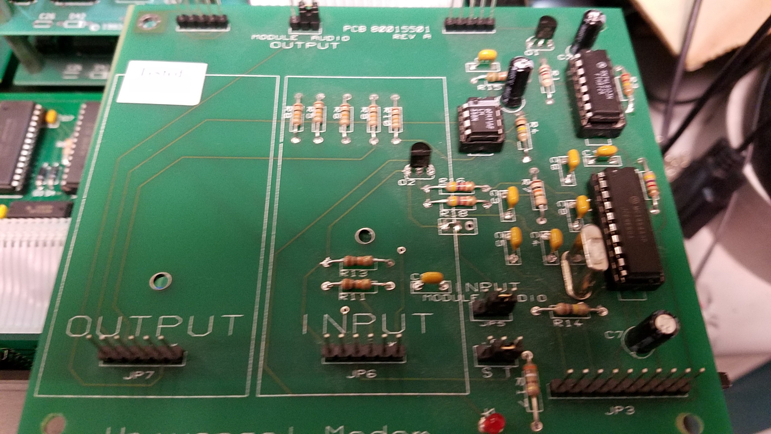
The 20 pin next to the crystal is a modem chip. Part MC145443P. UART enters this chip and it's modulated for the 4 wire Analog.
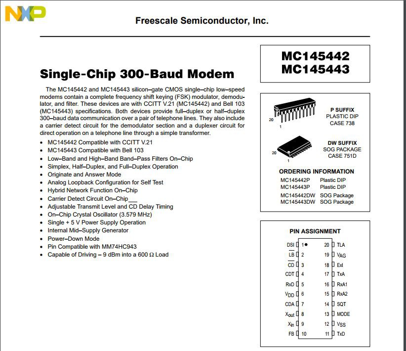
Pin 5, 6, 11, and 12 will do the trick. I'm removing the chip and using the 5 VDC to run the level shifter, the ground and RxD and TxD pins will round out what we really need to communicate.
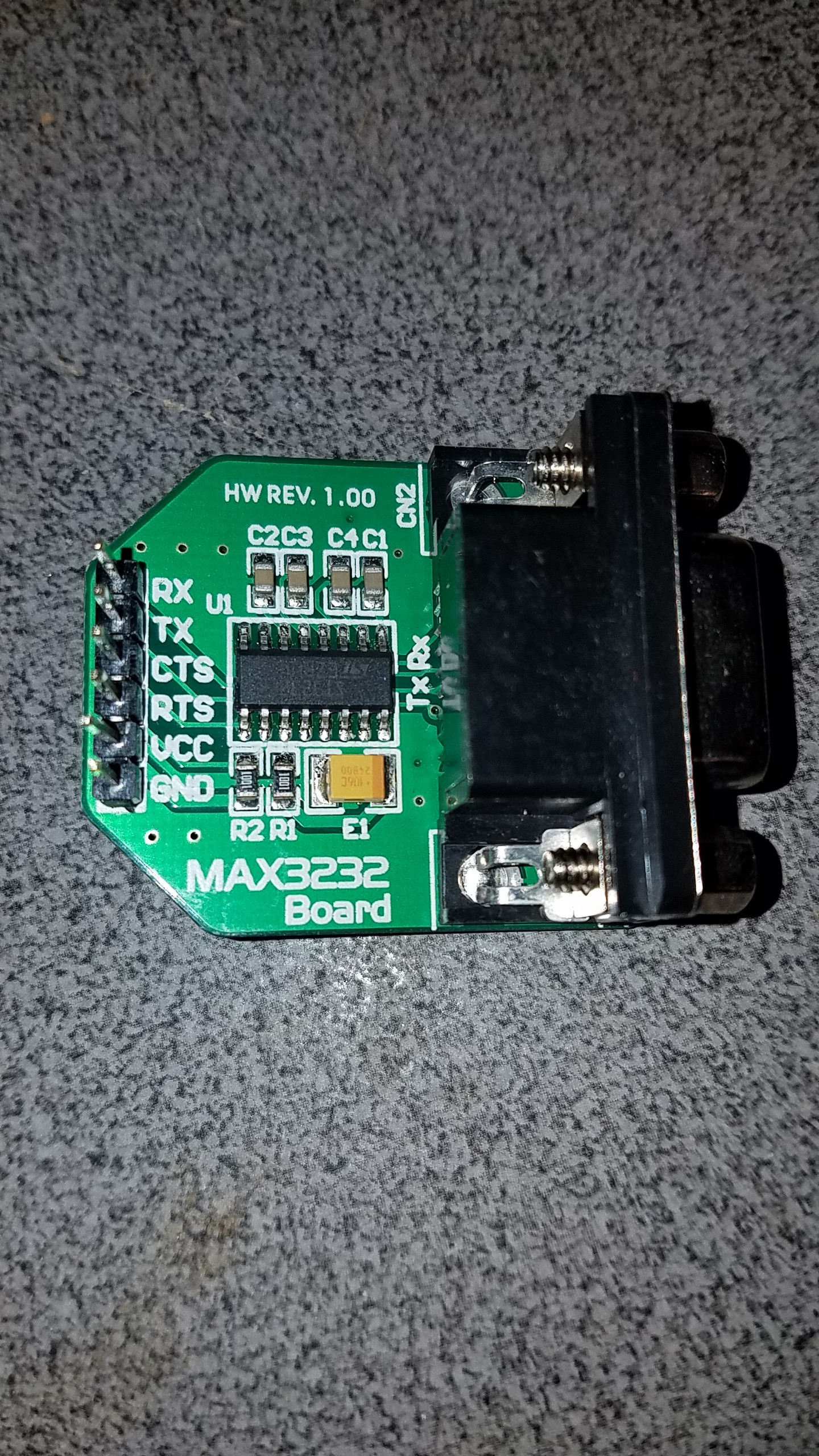
Now the levels aren't enough to trigger the signaling on the Comtrol devicemaster. I'm using a MAX3232 board for the level shifting. At $10 or less each, they save a lot of guess work in rolling your own.
I removed the socket from under the chip and just soldered in the wires where needed.
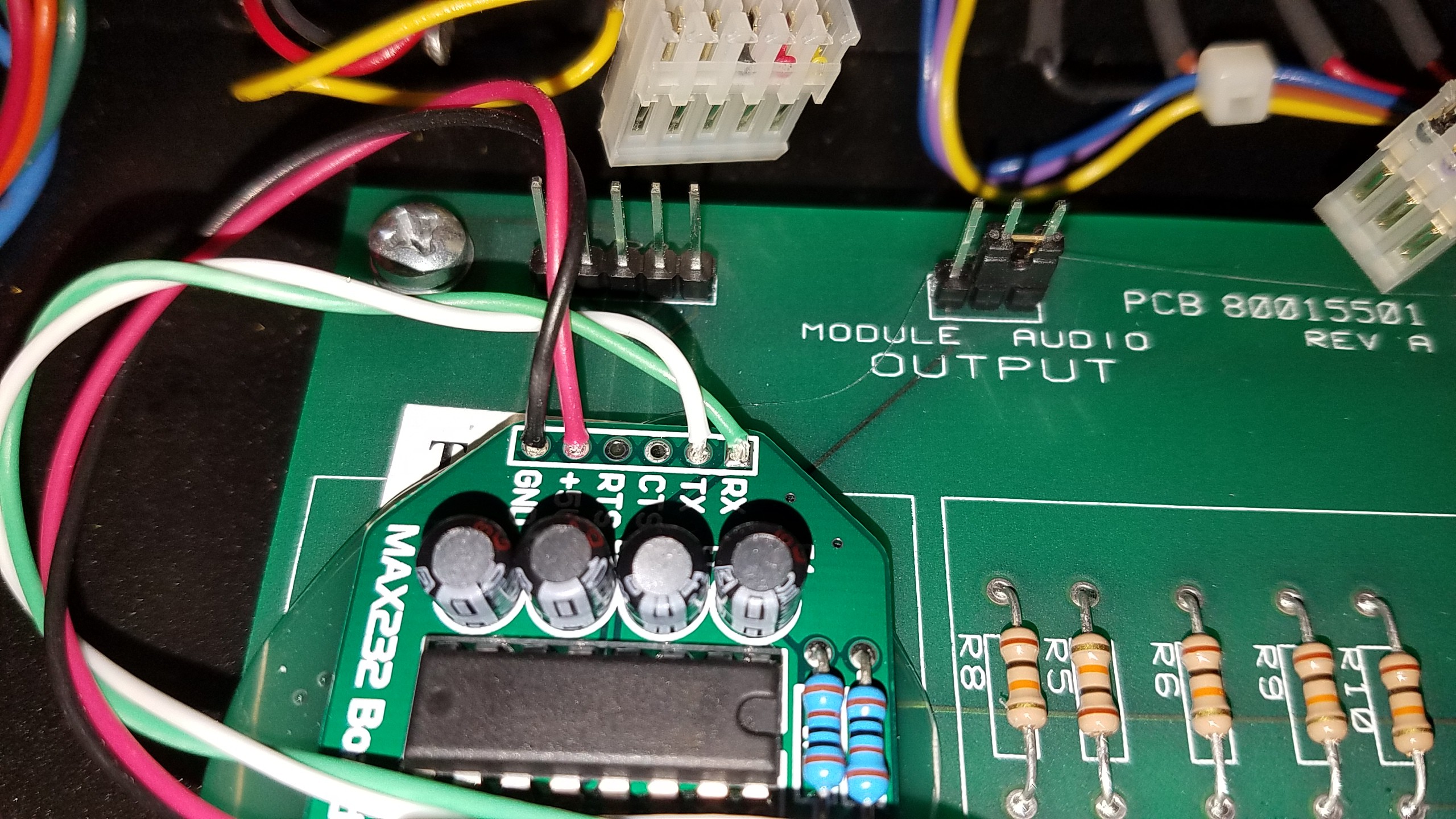
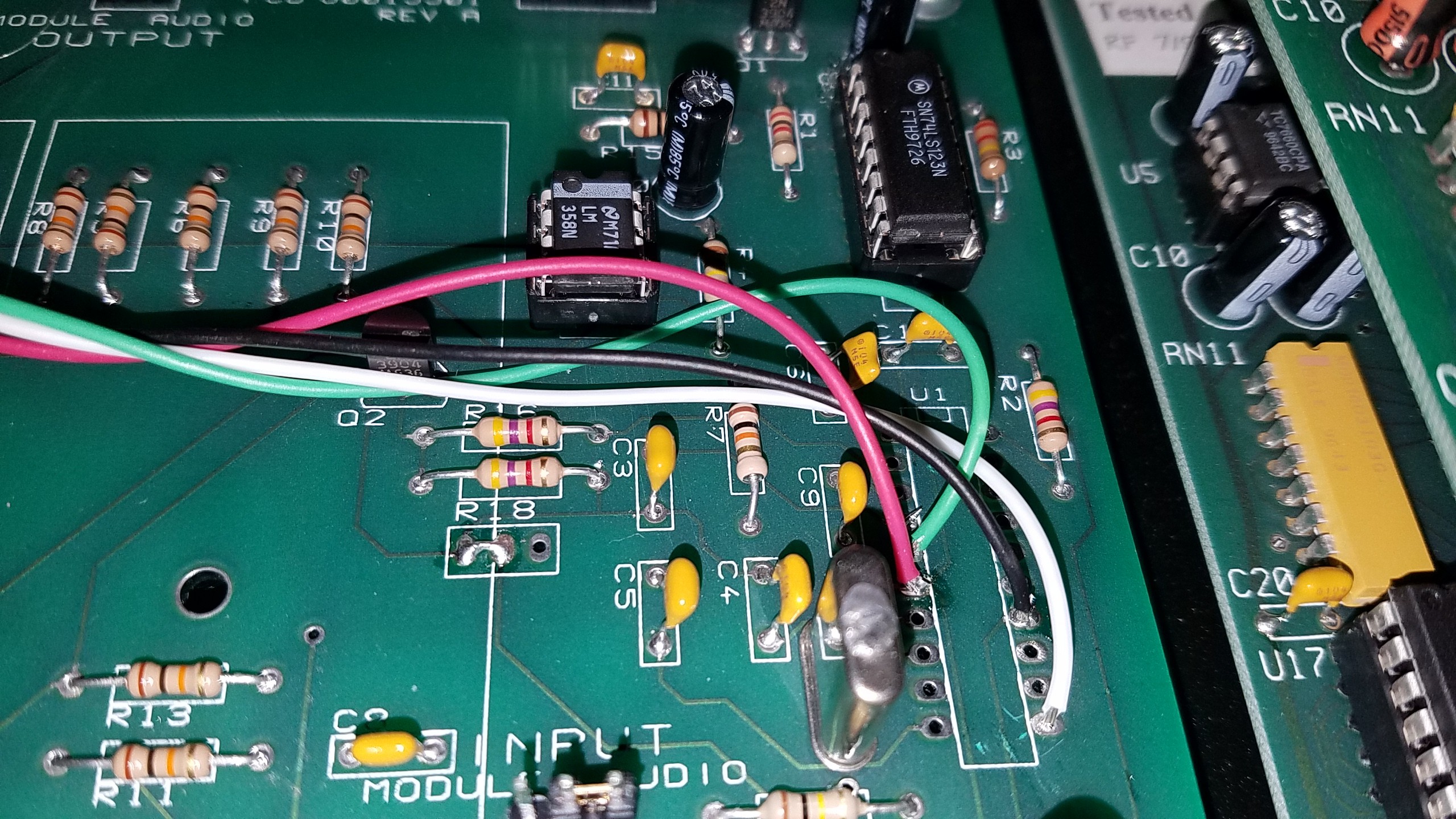
Noticing that pin 14 was also a ground point and a jumper was in use under the board to make the connection to pin 12, I used 14 in my wiring and removed the modification by the manufacturer.
Had a problem building the second unit where I had swapped the ground and 5V lines. I fixed that but then ended up with only TX working, no RX. Went through long diagnostics to determine where I had gone wrong or blown up. Turns out in the reset of the wires to their proper positions I left the iron on too long and ended up shorting out the 5V and RX lines together. This short was where the wire had melted and come together. If I hadn't been ready to scrap all the wiring and begin again I'd have never found it. (Fail of the week? Took me about a week of small time snippets to find it. Note this isn't my primary job to convert this, so I got maybe 30 minutes every 3 hours or so to dig into this.)
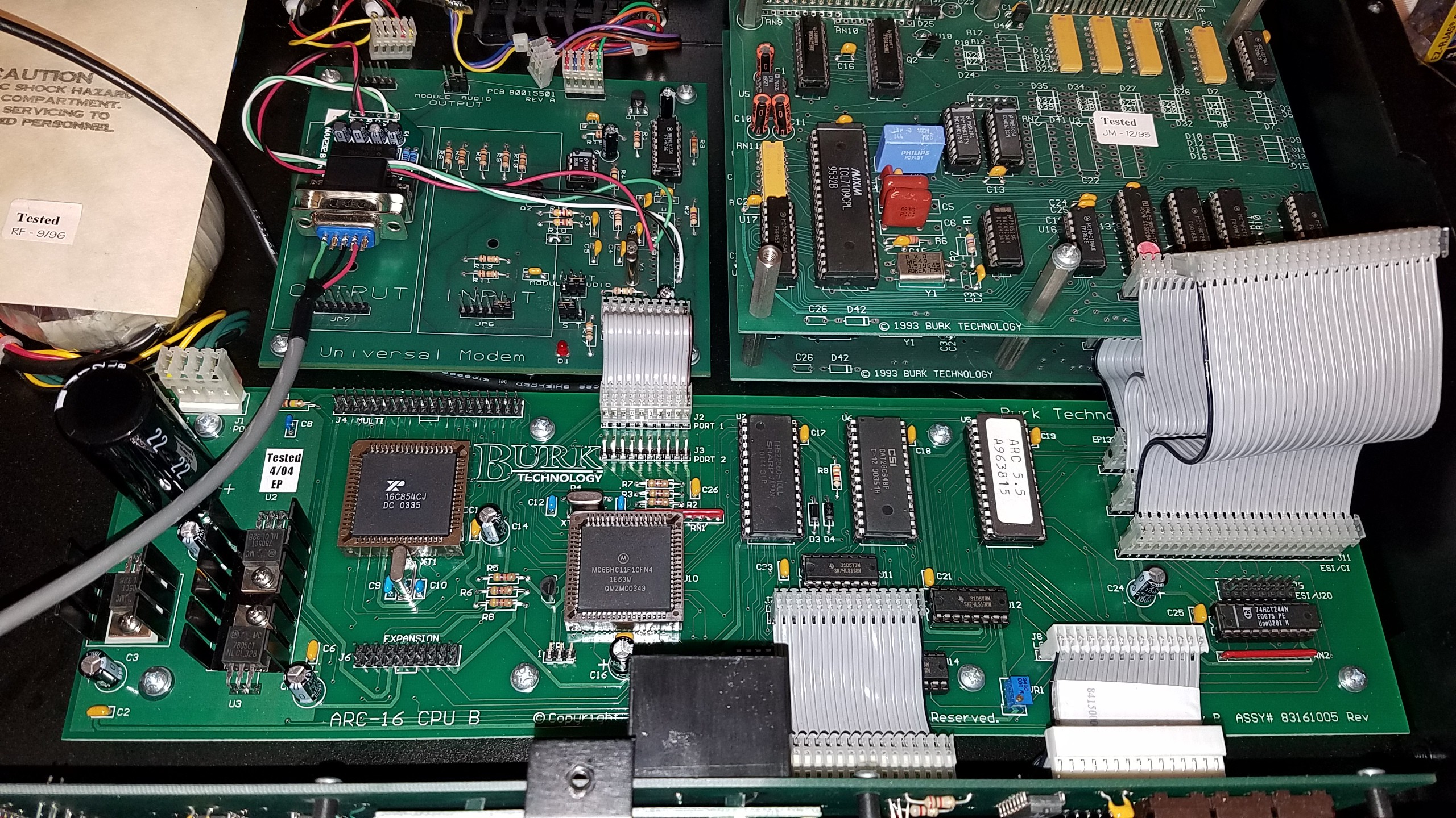
A bit of hot glue to secure the Max 3232 board and we're in business.
 RoboMonkey
Discussions
Become a Hackaday.io Member
Create an account to leave a comment. Already have an account? Log In.