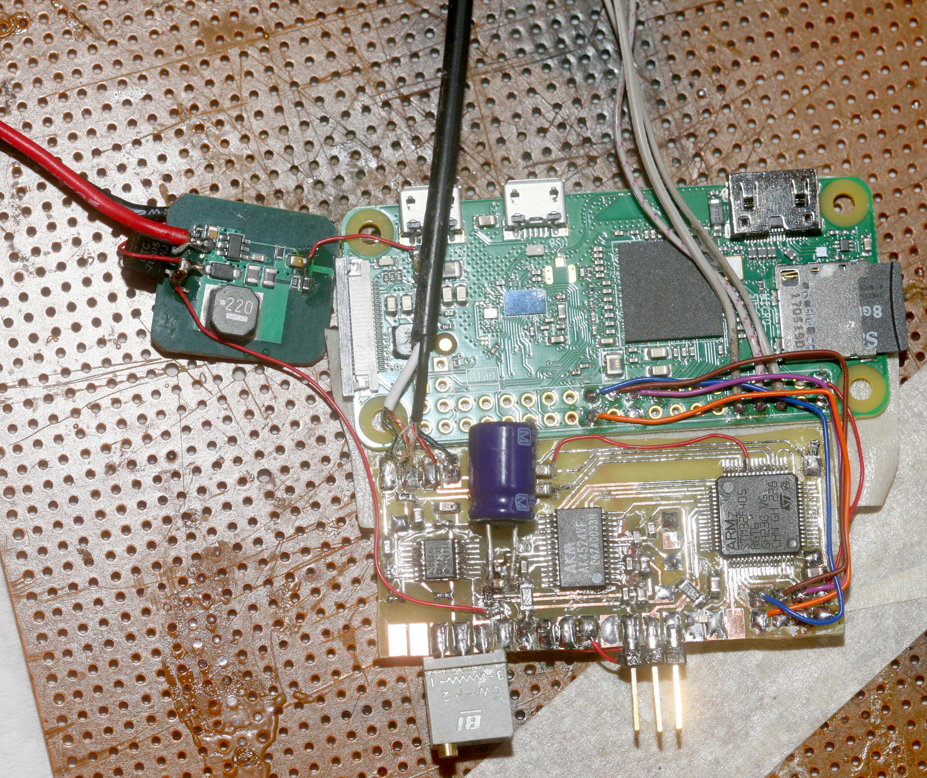
Powering the analog side off a dedicated battery was actually quite noisy. It still needed a 35R + 1000uF in addition to the 10uF & .1uF in the design note. This didn't create a warm & fuzzy feeling.
There was another experiment in powering the PI & analog side off a common 8.4V battery. The PI side was dropped through a 5V, then a 3.3V stage. The analog side was dropped through a 130R + 1000uF. It had a Xena diode protect it from overload. LTSpice predicted 100uV of ripple. This still had audible but very faint pulsing from wifi.

In a past life, it was a total failure to use a linear regulator & a resistor to filter power, but the decision was made to wack a 78LS05 + 70R + 1000uF in the analog side while keeping the PI on the 5V + 3.3V chain & powering both from a common 7.0V.

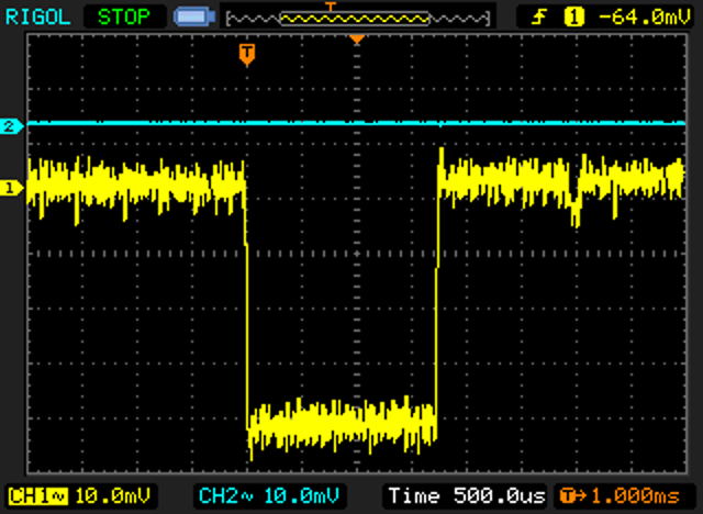
The oscilloscope with 32x averaging showed a quite impressive flat line for the analog side & the usual 40mV pulsing for the 7.0V input. The 78LS05 + 70R gave 3.2V to the analog side. The linear regulator was fast enough to knock out the pulsing while the RC knocked out a significant amount of the remaneing noise. Noise was not acceptable, directly off the linear regulator. The 5V & 3.3V stages leading to the PI were also unacceptable because of pulsing. The 70R + 1000uF were quite necessary.
This circuit is quite bulkier than what was envisioned but does what's necessary. It's quite impressive that the analog side can now coexist with the digital side after where it began & it might even be better than the CM109.
 lion mclionhead
Discussions
Become a Hackaday.io Member
Create an account to leave a comment. Already have an account? Log In.