For fear of the op-amp obliterating the waveform, was powering it down & tying the audio pin to ground through 10k to test the noise of the ADC. It turned out, turning the gain to 0 with the op-amp on actually gave less noise on the ADC. Perhaps it was the ADC being actively driven by the op-amp, but the op-amp definitely wasn't injecting noise at 0 gain.
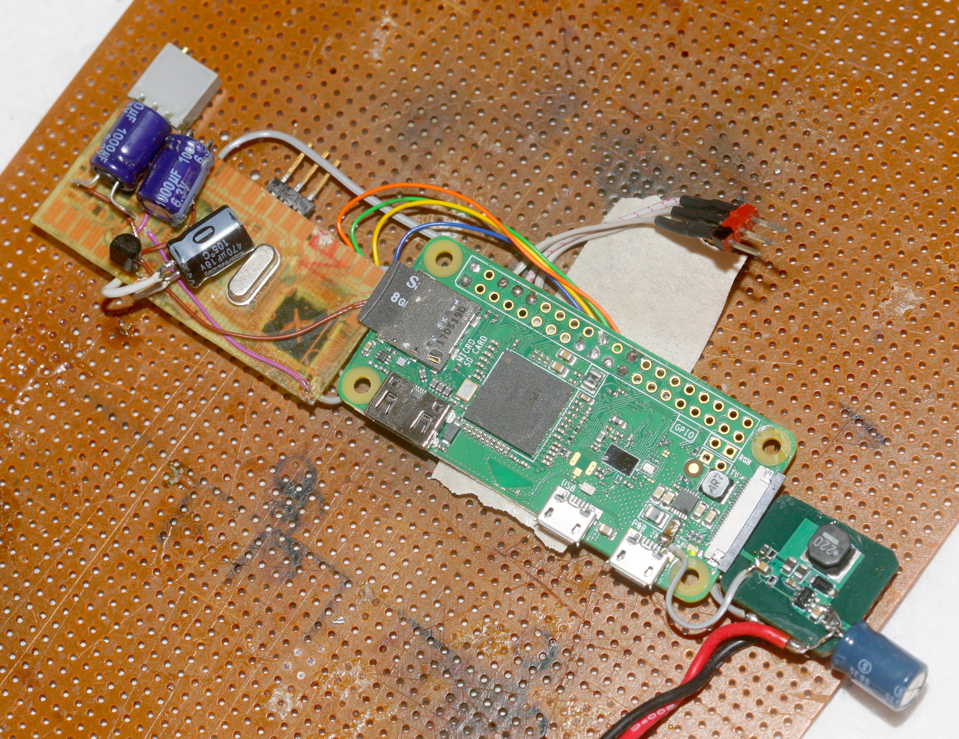
A test with a 4700uF cap made no difference. Moving the 8V-5V converter away from the PI improved it. With the op-amp at 0 gain, the analog section upside down, the waveform was decidedly showing the low 14 bits. Suspect it's noisier because some traces had to be longer than the dead bug. Mounting the boards end on might be adding more wifi interference. Without a flood filled ground, metal film resistors, RF shielding, differential inputs, digital pot, double sided load, it's not going to be perfect. This was the waveform at 1/262144:

The scene with the final converter placement:

 lion mclionhead
Discussions
Become a Hackaday.io Member
Create an account to leave a comment. Already have an account? Log In.