 George Albercook
Talking to the chip that does the communication between the remote control and the quad:
RF communication is done with the XN297L 2.4GH transceiver chip. We want to insert ourselves between the controls on the remote and the XN297L chip also on the remote.
Here is the controller opened up.
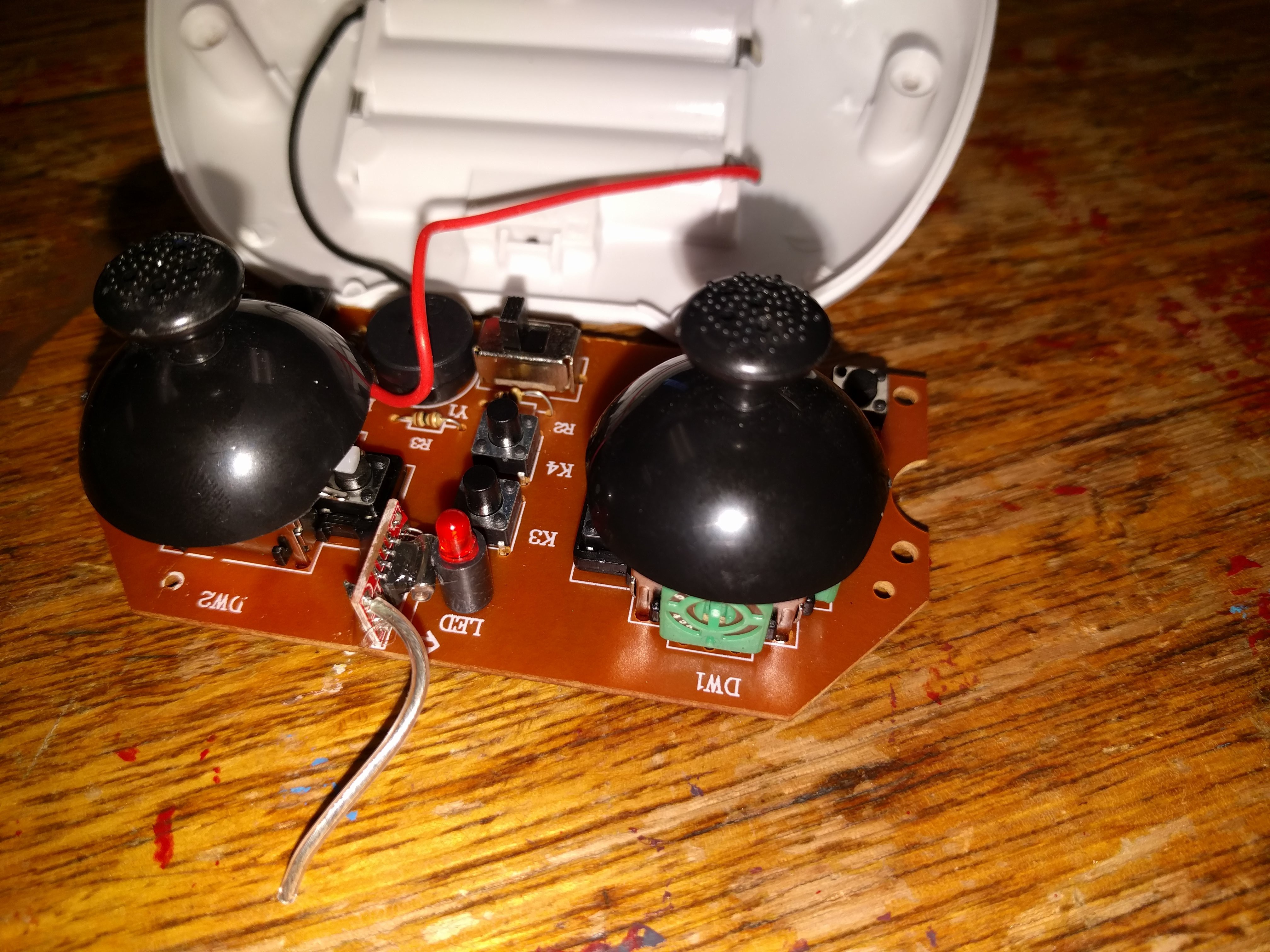
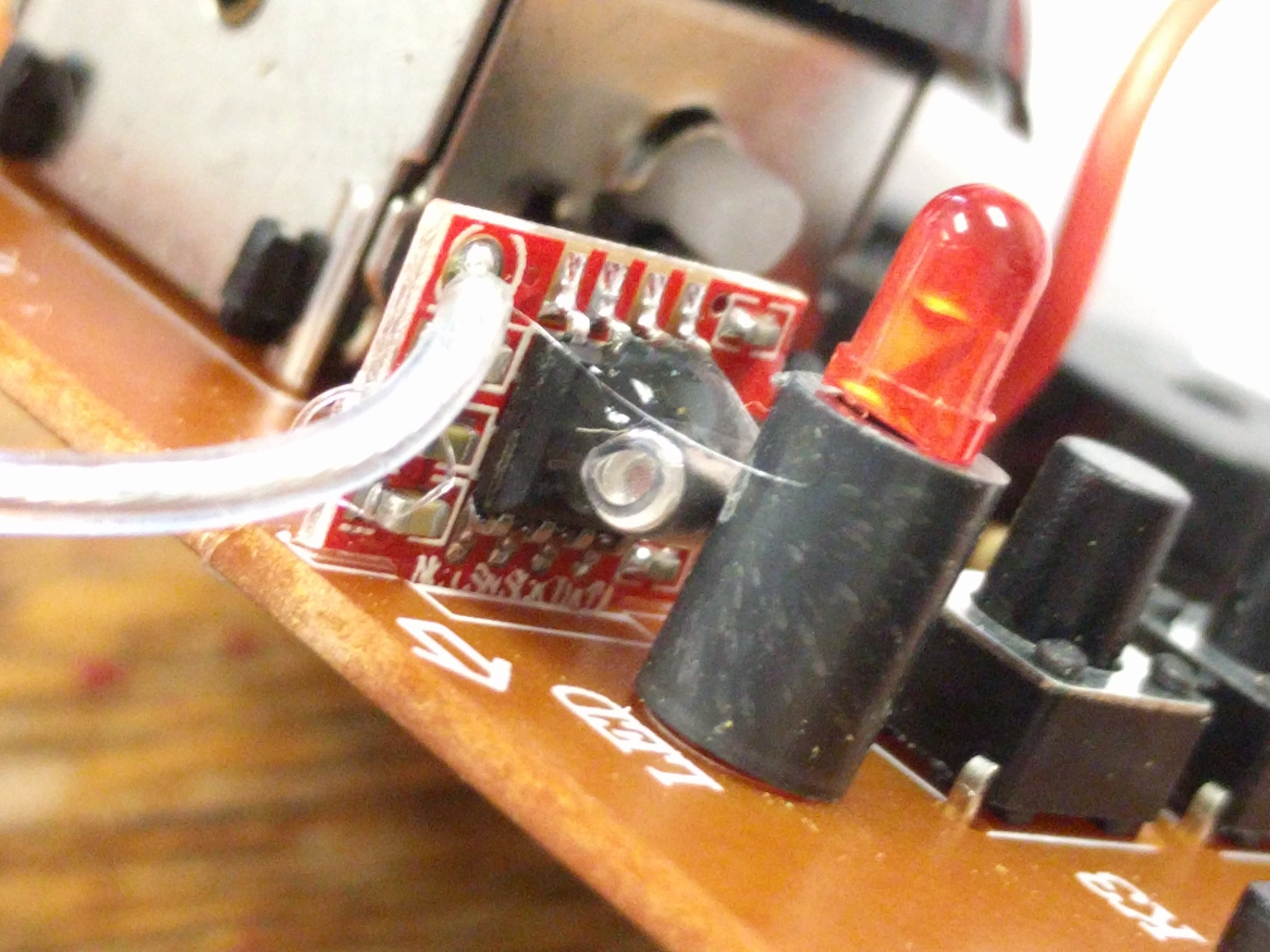
That little daughter board standing on edge has is the XN297L on it.
Here is a closeup.
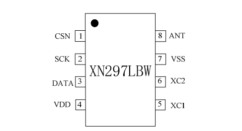
From the pinout we can tell which pins we want to intercept.
We will cut in on the back side of the board
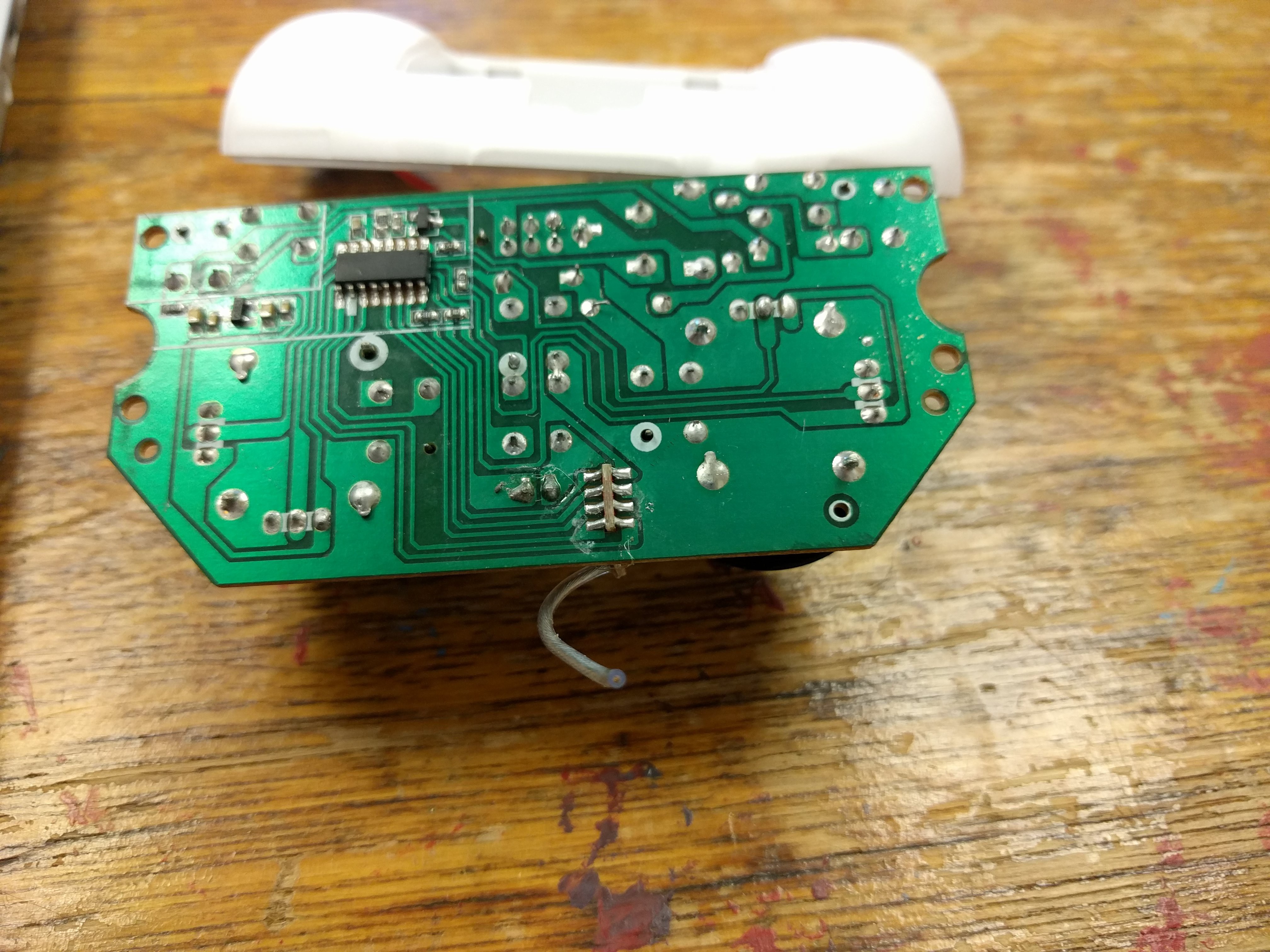
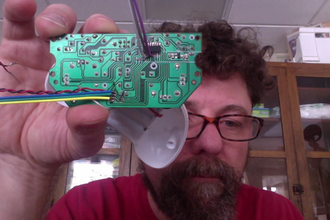
If you follow the traces from the Blue, Green and Yellow wires you can see that the traces on the PCB are cut. The other ends of the traces go to the chip.
Purple and yellow is Chip Select
Blue and White(with black strip) is MOSI
Green and Gray are Clock
Now we need to be able to read write signals to our wires. The protocol used is called SPI. The flavor that we are using is three wire SPI. So now we will set up an Arduino to speak SPI.
Discussions
Become a Hackaday.io Member
Create an account to leave a comment. Already have an account? Log In.
Purple and yellow is Chip Select
Blue and White(with black strip) is MOSI
Green and Gray are Clock
I didn't understood that
Are you sure? yes | no