 Niel Malan
I've finished this project. Today I soldered up the second board, tested and installed it.
Connectors.
The slots for the 3-pin connectors with their 3.5 mm pitch pins that didn't fit the Veroboard I made with a Dremel tool with a small, ball-shaped, diamond bit. This went much faster than the method I used on the first board, which was to carve the little slot with a pocket knife. The slots came a out little too wide, which made soldering more difficult. The solder would not naturally make a solder bridge between the pin and the track, because the gap was too wide. I solved this problem with a small, fiddly, U-shaped wire bridge, that I soldered on the tracks.
A lot of the work on this project went into making these connectors fit. I'd recommend buying the right things. I could also have taken wires from the board to chocolate blocks, but that's really a bit crude, isn't it?. And I had the screw connectors and I wanted to use them.
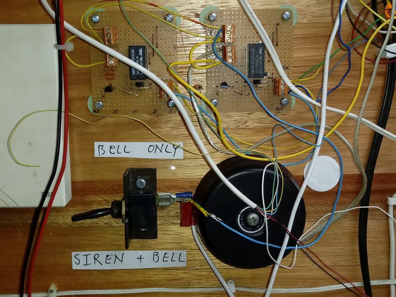
A thousand words:
Discussions
Become a Hackaday.io Member
Create an account to leave a comment. Already have an account? Log In.