 SimpleTronic
Quick Tour Video:
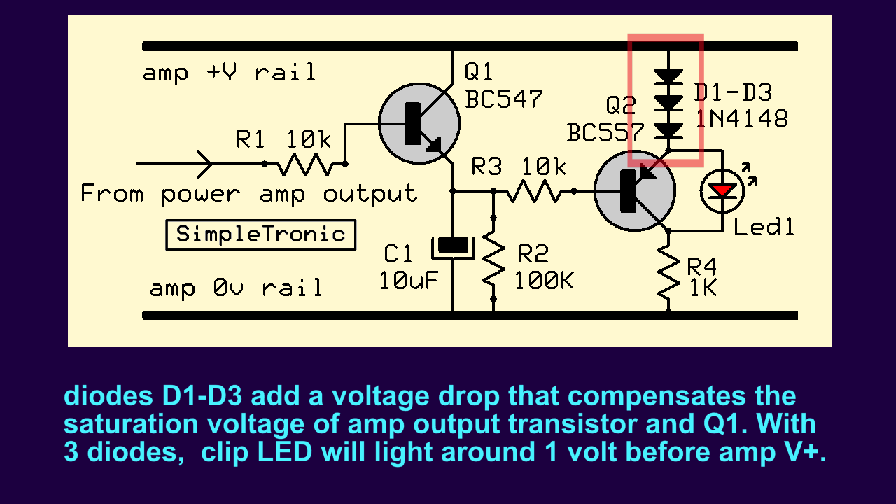
Circuit Diagram:
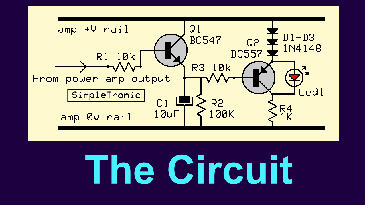
This circuit is suitable for low power amps ( up to 40v +v). Tweak the value of R4 for a LED current around 20mA.
For higher power amps use the circuit at the bottom of page.
Circuit for higher power amps ( v+ above 40v ):
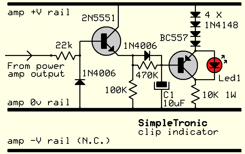
Tweak the value of R4 for a LED current around 20mA.

 greg
greg
 Silícios Lab
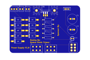
 Hamza Deniz Yılmaz
Caution: Looks like the max reverse Vbe voltage for Q1 can easily be exceeded, leading to degraded performance or outright failure.