 ho june
My HV5622 serial-to-parallel converter's recommended operating voltage is 10.8v to 13.2v. I wanted to use 12V logic on it, but my MCU uses 5v logic. So I used a MOSFET-based level shifter(The circuit based on this site).
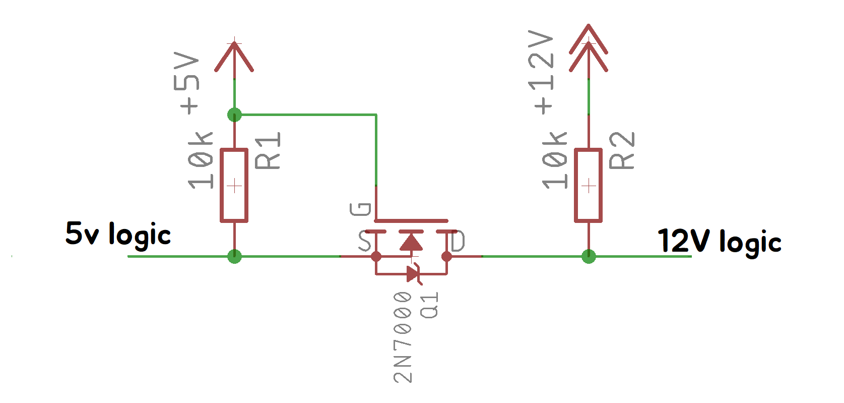
I tested the circuit in my breadboard. The 5v logic connected to the switch(Don't let a pin floating in logic low!) and the 12v logic connected to the multimeter.
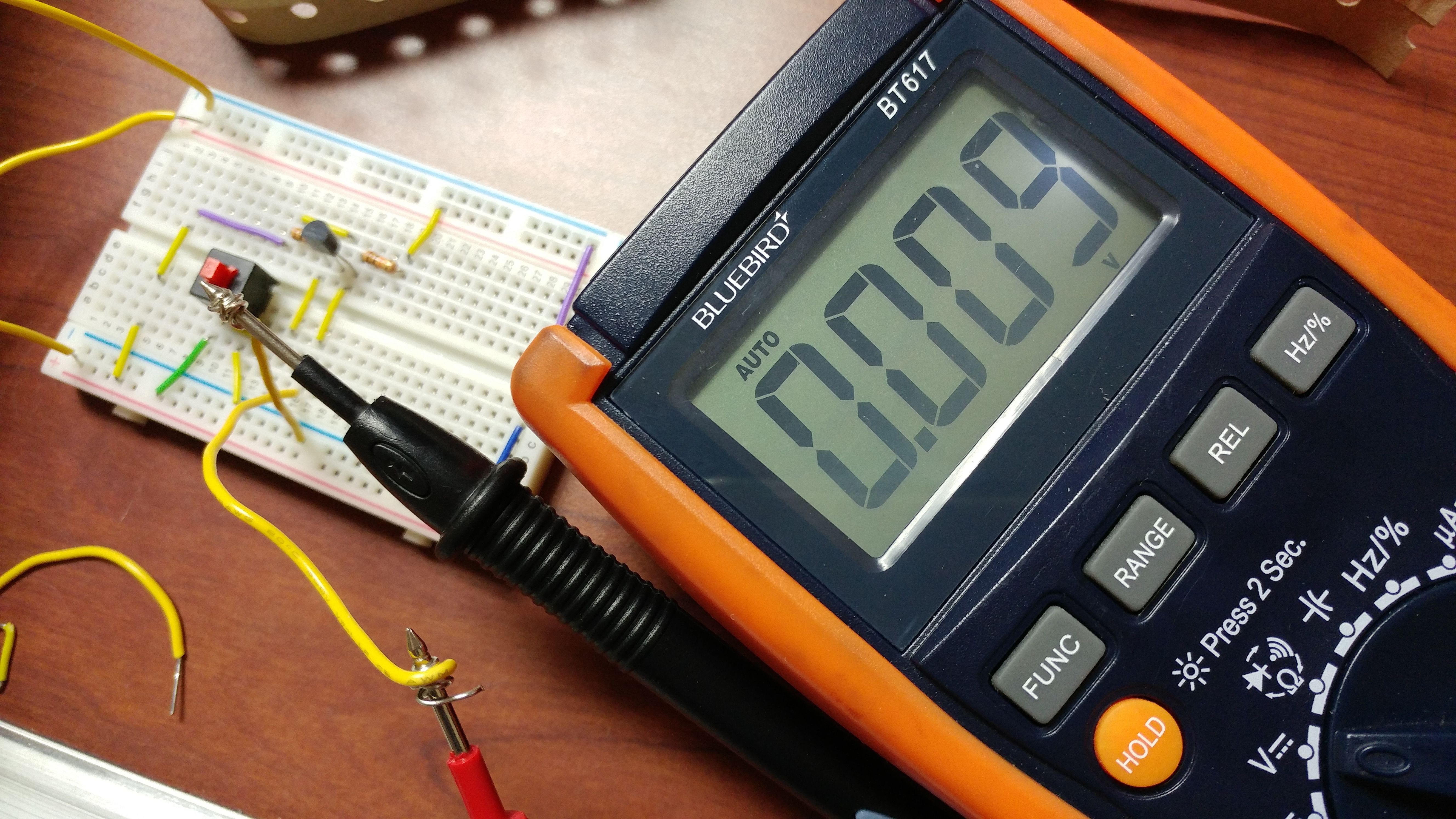
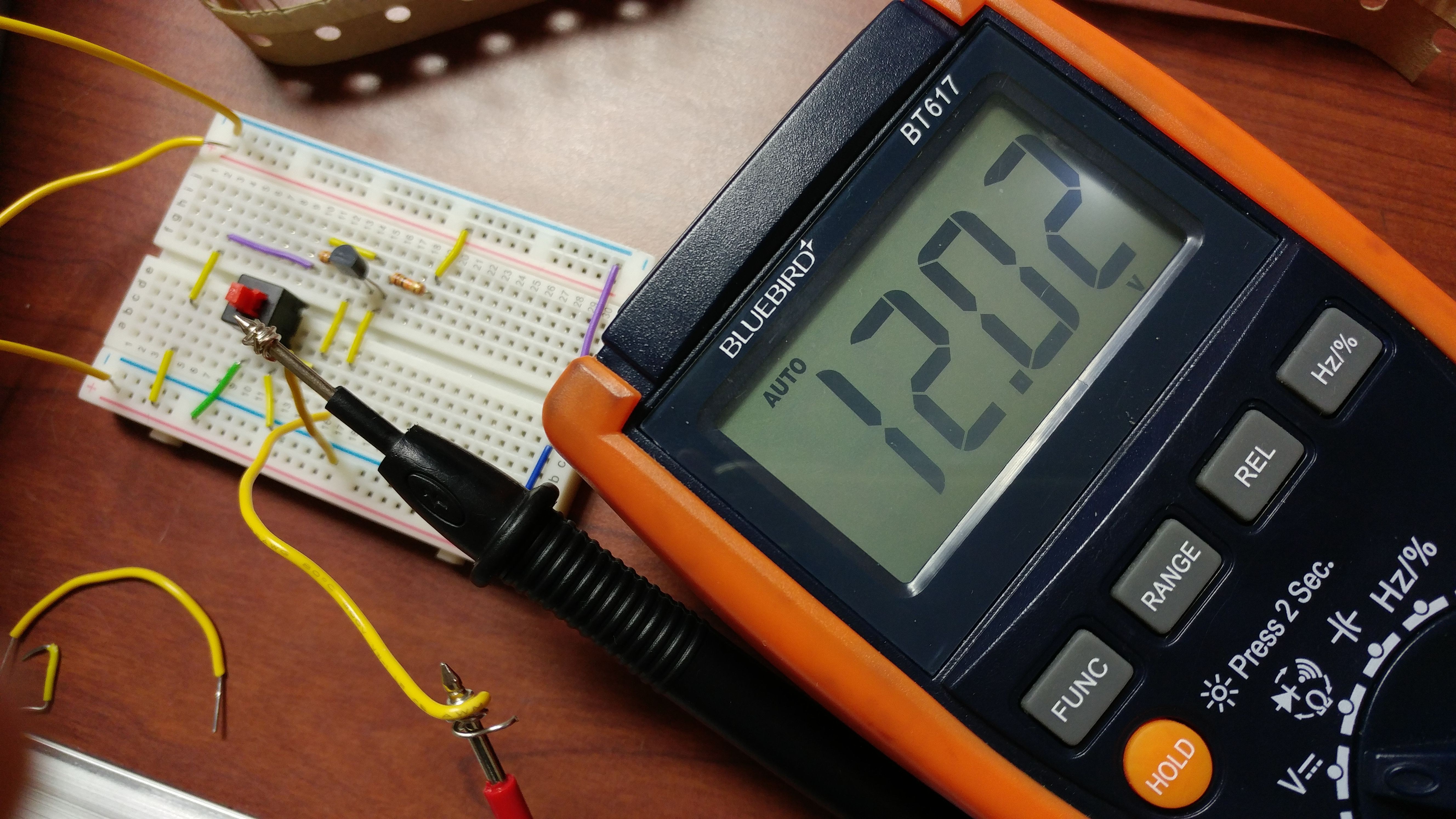
That's great!
And I'm doing PCB design of my nixie clock's main board these days.
Discussions
Become a Hackaday.io Member
Create an account to leave a comment. Already have an account? Log In.
Forgive my ignorance but is this design bidirectional? Does a voltage on either side activate the opposite side?
Are you sure? yes | no