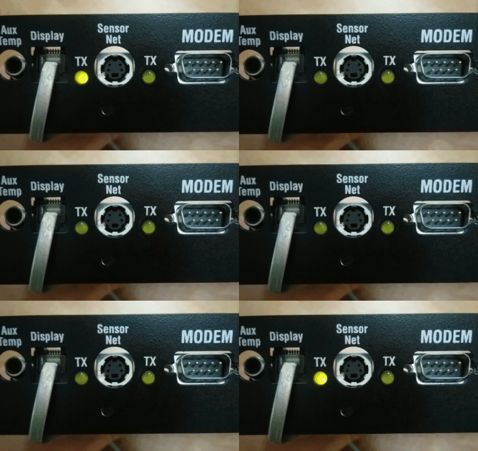
With no sensors connected, I put some RJ11 between the boards and powered them on. To my surprise, "NO SIG NAL" disappeared, and was slowly replaced with what appears to be random data. Or, maybe, the MCU is interpreting the null voltages from its sensors as max or min values. Who knows! I'm just glad to see something flowing, because it gives me something to sniff. I was worried that I'd have to spoof a PS/2 "Sensor Net", whatever that is!
I don't own a proper logic analyzer. However, I do own an arduino! So I dropped in the excellent work of [Andrew Gillham], a SUMP-compatible logic analyzer for arduino.
The results show that the "dim LED" isn't dim, but instead, directly connected to the transmission line! It's dim because it's transmitting serial data on and off. I wonder about the effects of the diode on the transmission line...

I see also that it's sending 100msec of data every 1sec. The narrowest gap I measure appears to be 79usec, which would correspond to something like
Putting a serial monitor on the line spits out data, but it's not necessarily good data. As soon as I figure out how to use SUMP/OLS to decode serial data, I'll know more. I'd like to record the stream and try to replicate it, then change parts of it to determine what is written to which 7-segment.
Discussions
Become a Hackaday.io Member
Create an account to leave a comment. Already have an account? Log In.