Yesterday I designed enclosure for my LLG in FreeCad
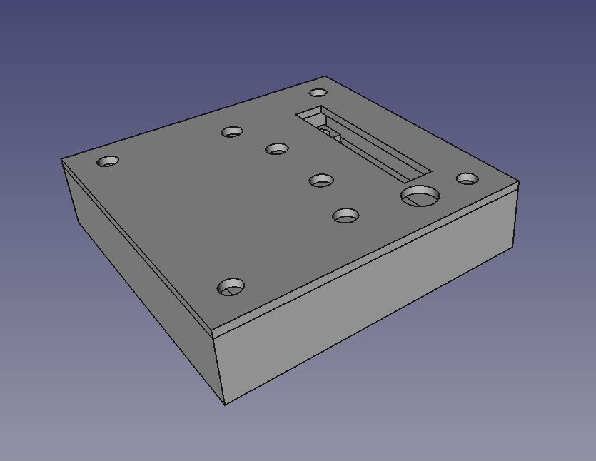 and printed it in two parts
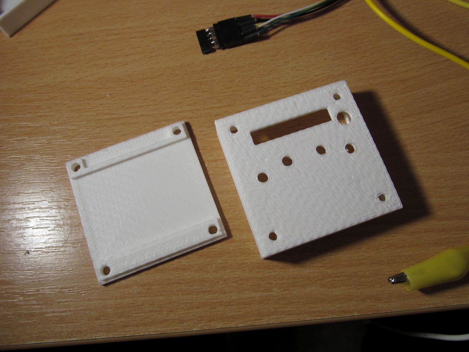 After a few strokes with sandpaper it fitted nicely together, bottom part first, with standoffs
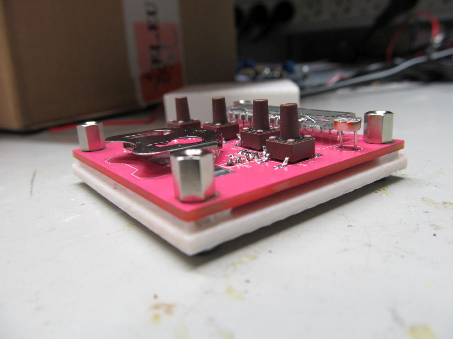 inserted battery
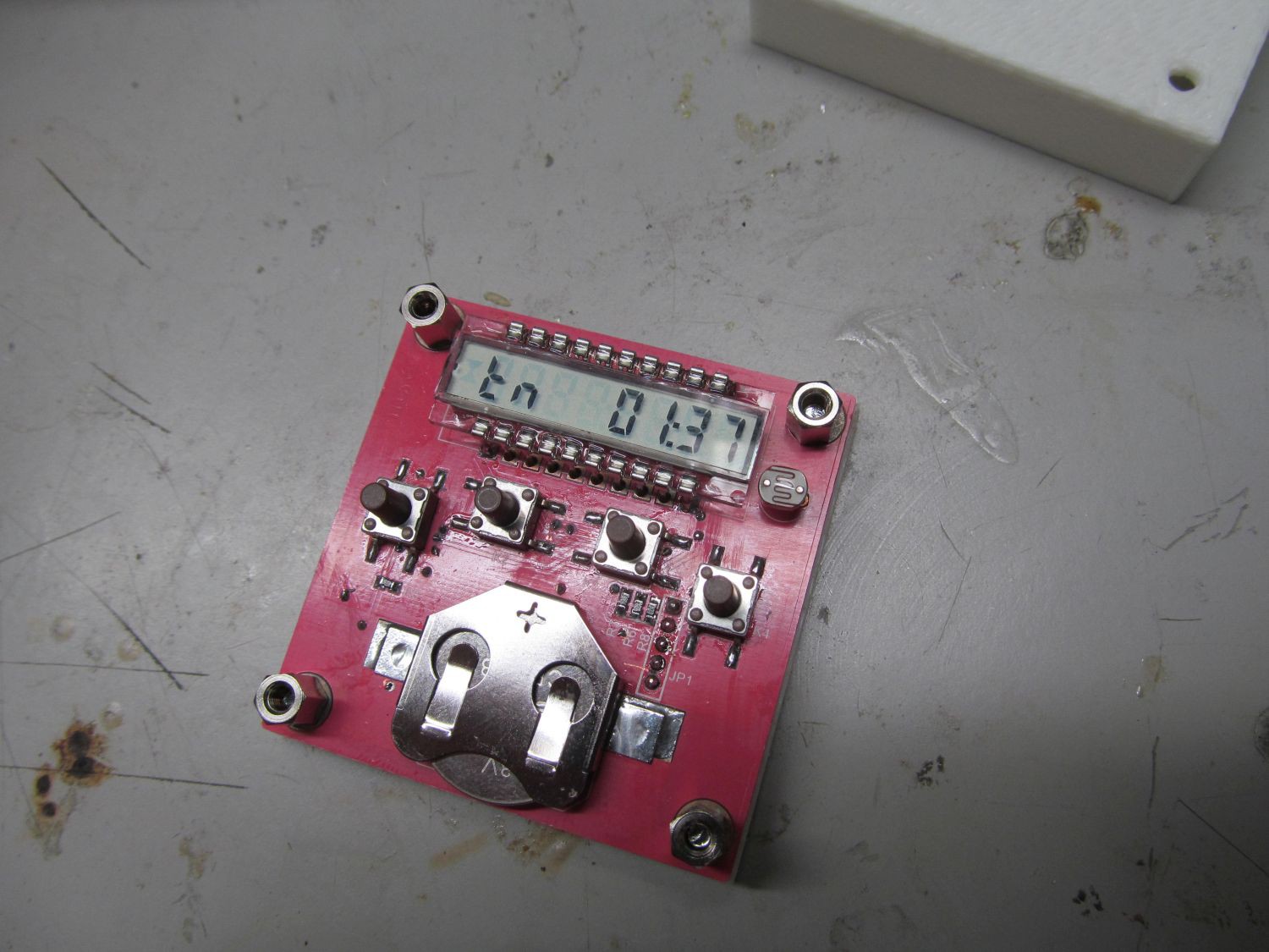 and top cover
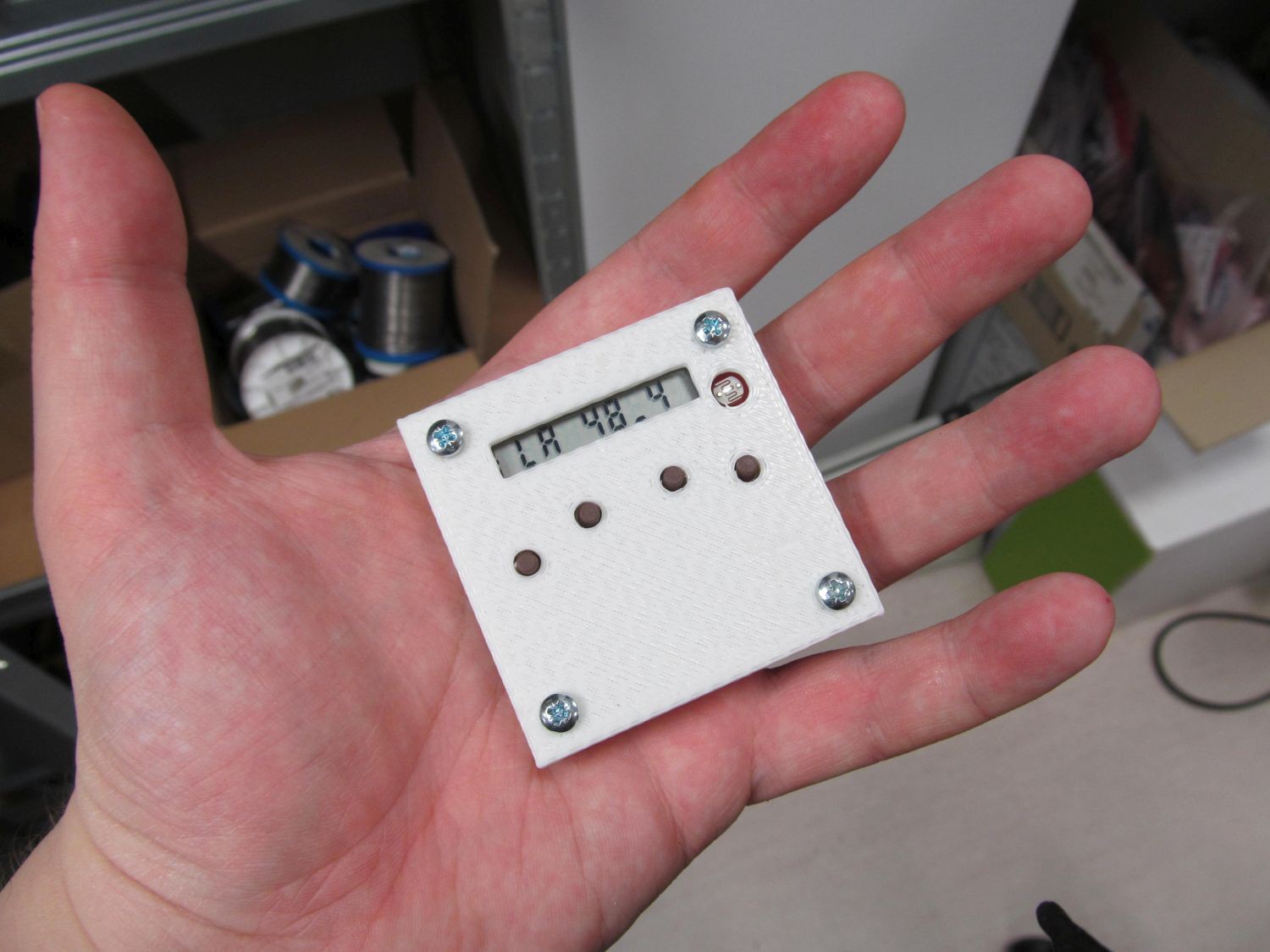 While case was being printed, I made final touches to my firmware I was working on for last three days. As this project reaches to completely new filed to me, at least 95% of code was freshly written, with little code reuse.
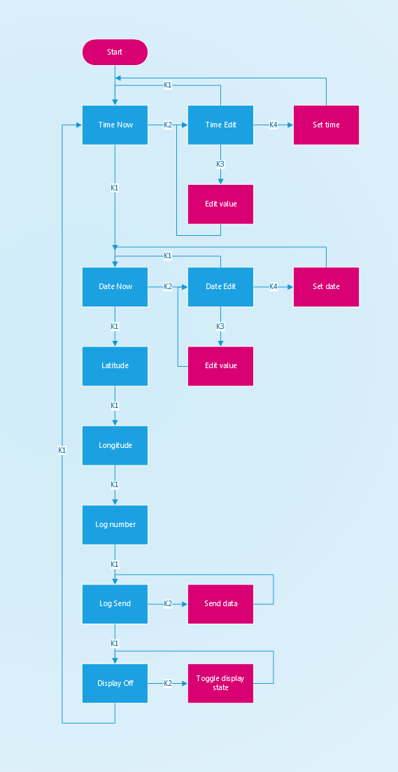
User interface of the LLG is being built around four key switches and LCD. The switches are numbered K1, K2, K3 and surprisingly K4; left to right. In general, K1 changes current display content, K2 selects what to change, K3 does the change and K4 is here to confirm the change.
Flow diagram of the UI logic is as follows:
 When browsing UI, device is clocked off internal 31kHz oscillator, with total consumption roughly 25uA.
After half a minute of inactivity device enters idle mode, with lowest possible current consumption, with two possible options - display on or display off. With display on, the consumption is roughly 2,5uA, without display approximately 570nA.
Every minute logger switches to 1MHz oscillator, then briefly powers voltage divider with LDR, takes one sample from ADC input where LDR is connected and saves the sample into RAM, then enters previous state. When midnight is reached and sufficient amount of samples is collected, geographical latitude and longitude are calculated, one record is written into EEPROM, internal variables are updated and device enters previous state again.
Here is video of LLG (without case) in action.
The video is 12 hours old, what unfortunately means it doesn't have display on/off feature captured. The switching sound of switches is actually quite modest, but the automatic gain control of camera microphone channel made it loud as if my bones were cracking or something.
I have to record another video, probably, and also make some battery life estimation.
Also, I setup github repository with various bits regarding LLG, I'm filling it on the fly.
 jaromir.sukuba
Discussions
Become a Hackaday.io Member
Create an account to leave a comment. Already have an account? Log In.
too bad it isn't transparent to show off the pink pcbs :)
Are you sure? yes | no
One can use it without front cover :)
Are you sure? yes | no
hmm, or laser cut a front from acrylic plastics - I don't say that often, but with pink pcbs I accept transparent laser cut fronts.
Are you sure? yes | no
@davedarko I agree the pink PCB should be visible., but iIt was one evening before contest deadline and I had zero laser cutters and one 3D printer in my home workshop, so choice was easy :-)
I had to make better time management next time, this contest was really tough.
Are you sure? yes | no