 Christoph Tack
Schematic explanation
Warning: This schematic is not a definitive version. Only the DTMF-generator has been implemented. There are no provisions yet for detection of pulses during dialing.
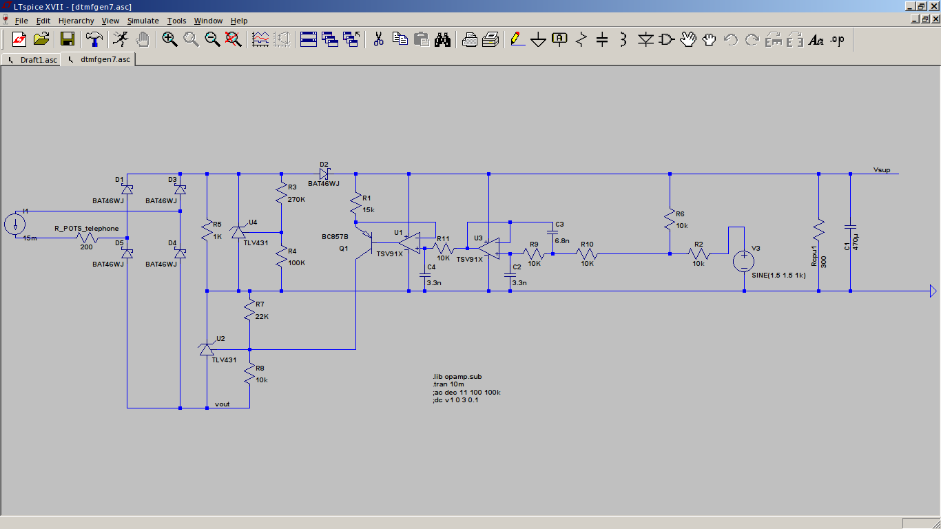
The schematic above couples DTMF to the telephone line.
- The current source on the left is the SLIC that sources 15mA to 30mA current.
- The R_POTS_telephone is the internal resistance of the off-hook telephone. You can see that the DTMF-generator is in series with the telephone line. When the telephone is on-hook, the telephone resistance is very high, so there's no loop current. This circuit doesn't consume power when the telephone is on-hook.
- The diode bridge rectifies the loop current, making this circuit insensitive to line polarity or line reversal.
- R5 not needed for generating DTMF, only during pulse dialing.
- U4, R3, R4 function as an adjustable zener. The "zener voltage" is set to 4.6V. This is the source of the supply voltage of the DTMF generator. So no matter what the loop current is, the zener behavior will limit the supply voltage to about 4.6V.
- D2 & C1 are not needed for generating DTMF. They keep the MCU going when the telephone is in pulse dialing mode. When these pulses are being generated, loop current is interrupted and the supply voltage of the DTMF-generator would collapse.
- Rcpu1 simulates the behavior of the MCU, drawing 10mA at 3V.
- You probably recognize U2, R7, R8 as an adjustable zener again. These three components couple the DTMF to the telephone line. We can modulate the U2-zener voltage, and hence modulate the total voltage over our DTMF-generator. This voltage is one-on-one transferred to the audio output of the SLIC. The drawback of this solution is that it adds about 2V to total voltage over the DTMF-generator.
- U1, R1, Q1 is a current source. By varying the current into U2, it's "zener" voltage will vary linearly.
- U3 with surrounding caps and resistors: An active low pass filter, desiged with Nuhertz Filterfree. For audio frequencies as used in this design, active filters are the way to go. Passive filters are either ineffective with RC or require very large inductors with LC realizations.
- R6, R2: Voltage shift and divider for the input signal to avoid exceeding the CM-range of the opamp.
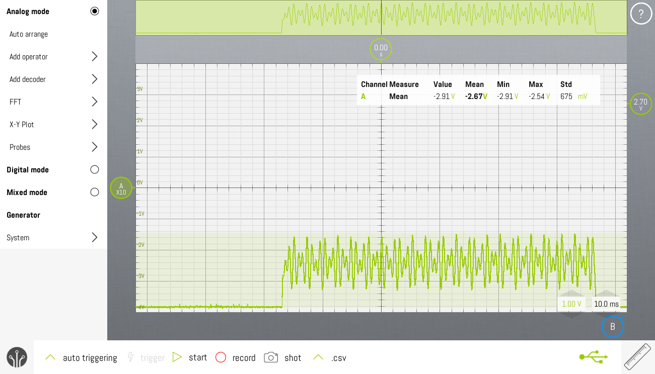
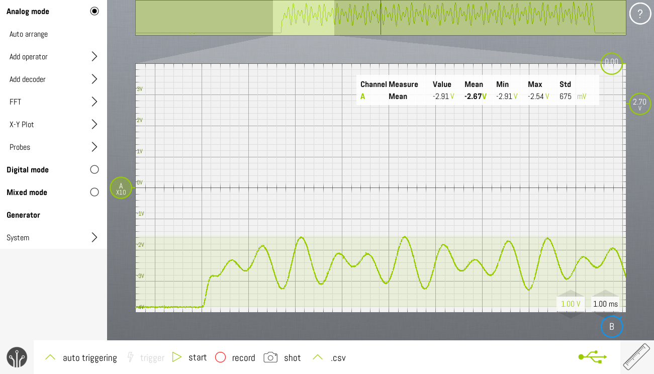
Measurements
The measurements show the voltage at the audio output of the SLIC. As you can see, most of the HF-noise has been removed and there's no noticeable deformation of the DTMF-waveform.
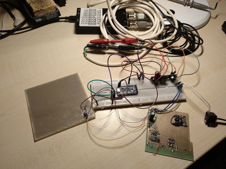
Picture of the current setup
There's not so much to see really. The breadboard contains the Adafruit Protrinket 3V and the SLIC. The 1.27mm-protoboard on the left has the opamp circuit on it. The 2.54mm-protoboard on the bottom right contains the TLV431 circuits. On the right, you can see the RJ11-connection to the telephone.
Discussions
Become a Hackaday.io Member
Create an account to leave a comment. Already have an account? Log In.
Like you said, there's no challenge in that. There's commercial hardware that does exactly what I'm trying to do here in this project.
An alternative approach would be to use single chip tone generators and audio coupling transformers. Easy to do. Any kid can wire some ICs together.
The fun lies in creating solutions with a small library of "standard" components that are used over and over again in different projects. Most of the times, this involves some analog circuit design. That's the beauty of electronics hardware.
Are you sure? yes | no
I like the discrete approach!
You probably already know that you can buy commercial DAA's that will all the line interfacing for you. At least you could at one point. But, there's little challenge in that :-)
Are you sure? yes | no