 Christoph Tack
Printed board assembly
Assembly is fairly easy. Be careful buying the BAT46W in the correct package. I've updated the PCB to revision /1, replacing the BAT46WJ (SOD-323) to BAT46WH (SOD-123). The -WH variant is bigger and easier to solder by hand.
Programming the board
I explained the procedure already in a previous log. To connect the programmer to your ATTINY85, you can use a Pomona SOIC-clip as shown on the image below.
Measuring interrupt frequency
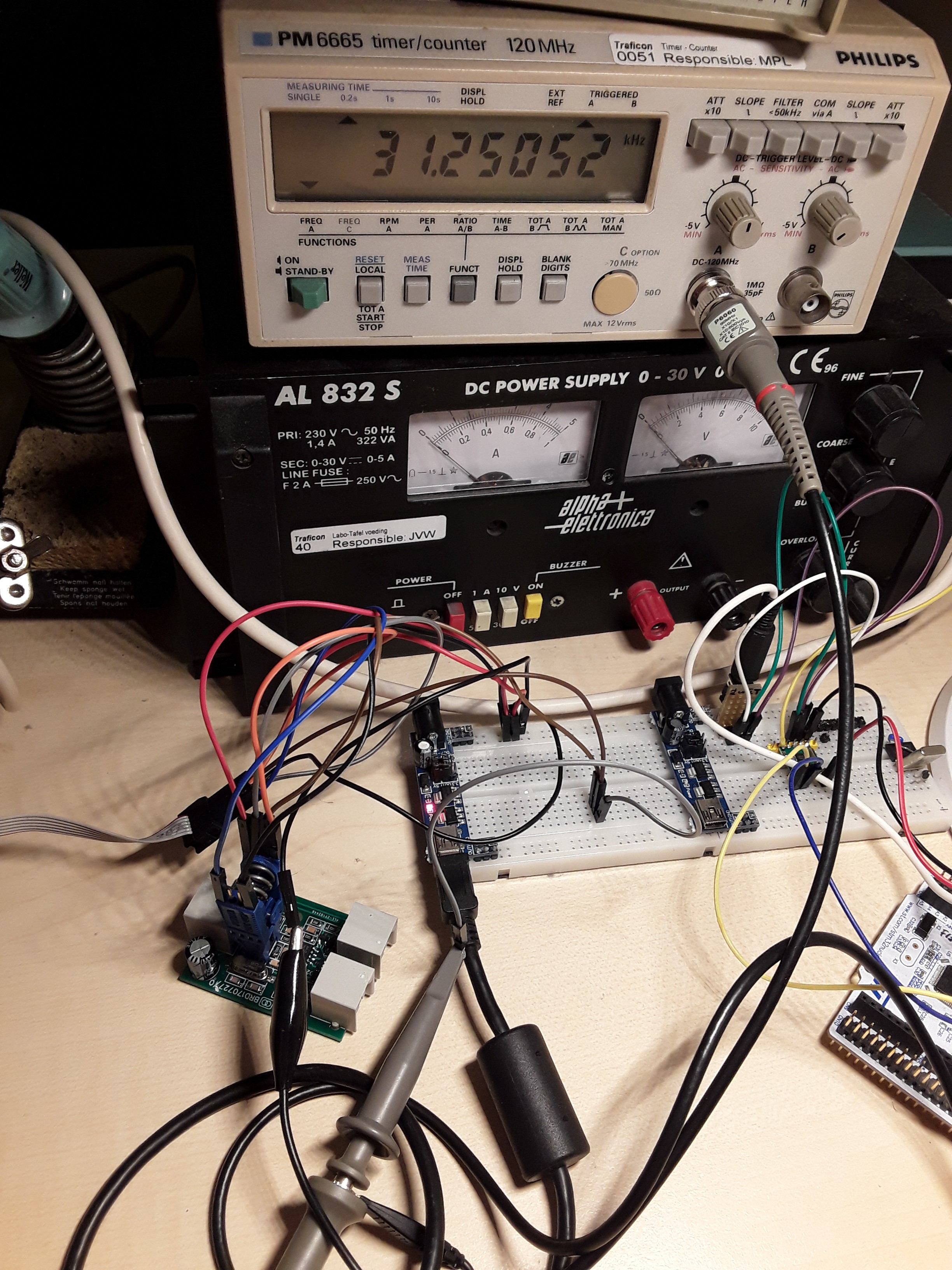
To check if the crystal has the correct load capacitors attached. A special debug firmware is loaded into the device which generates a square wave with a frequency that should be 31.250KHz.
Adjusting DTMF-amplitude
Someone reported that the DTMF-amplitude was too large for their application. Increasing R10 from 10K to 100K and R12 from 10K to 15K fixed that.
Mounting in the housing
The housing originally contained an ADSL-splitter. It can be bought for a few cents from AliExpress. Its PCB has been removed. The modular jacks have been transferred to the pulse-dtmf-converter.
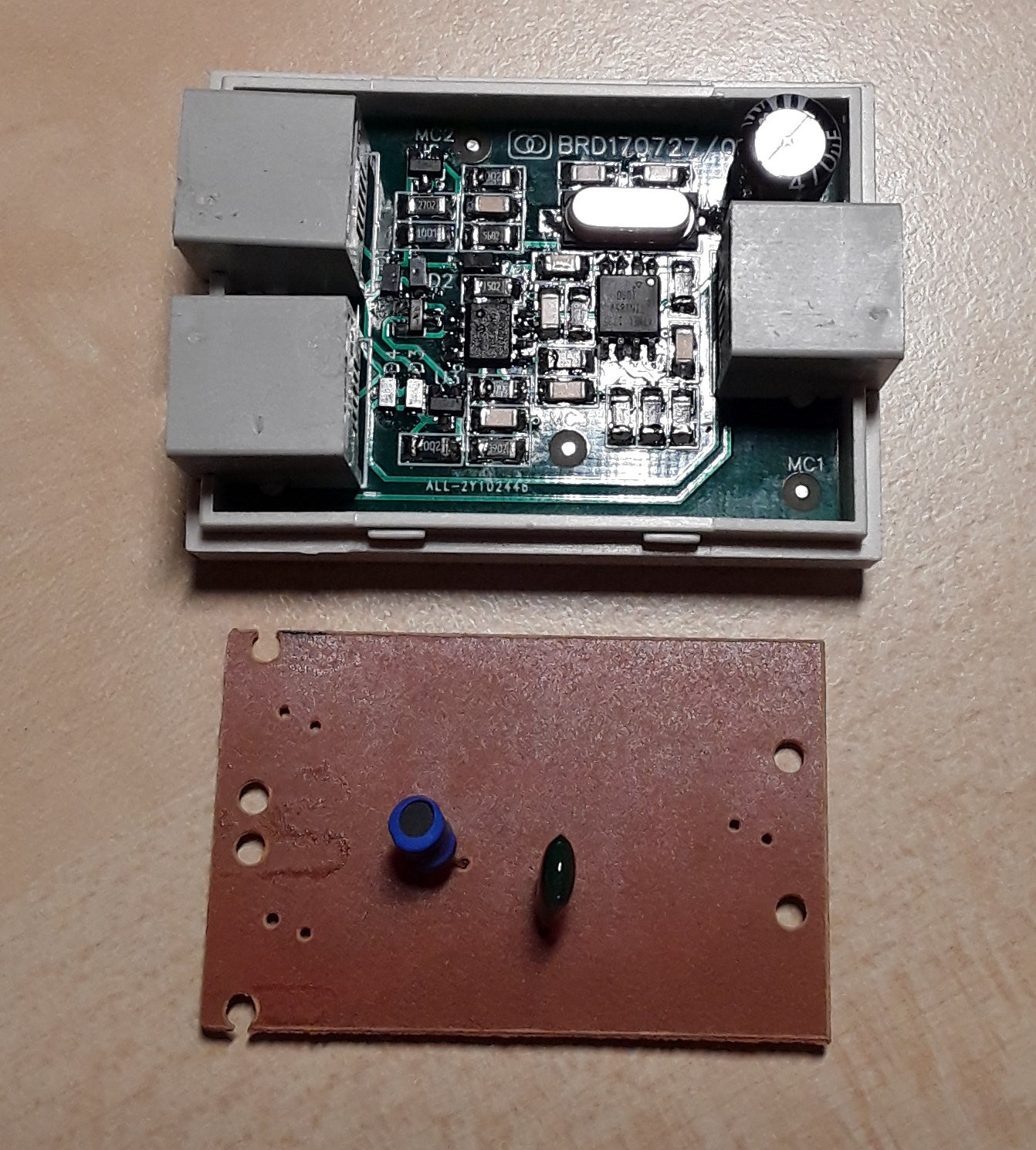
The PCB that was originally mounted is shown below it.
Finishing up
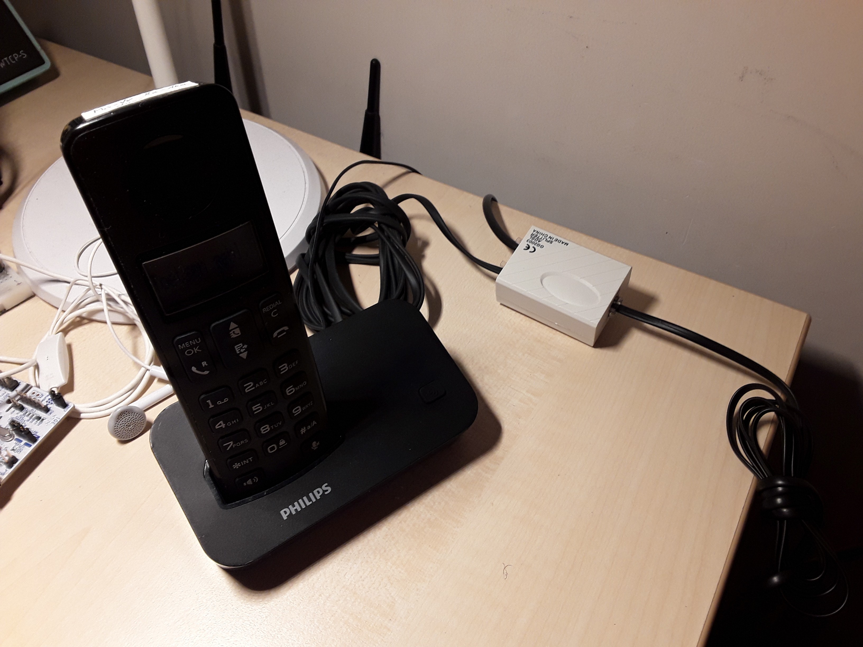
The Philps DECT-phone, which uses tone dialing is connected to the "PHONE"-port of the converter, as indicated on the bottom of the housing.
The FXS-port of the internet gateway is connected to the "MODEM"-port.
The pulse dialing phone is connected to the "LINE"-port.
Making a few test calls assured me that both phones are working well.
That's all, folks.
Discussions
Become a Hackaday.io Member
Create an account to leave a comment. Already have an account? Log In.