 Christoph Tack
Test environment
As the design process will require measurements and manipulations on a potential high voltage telephone line, we can make it easy for ourselves by making a complete test setup on our test table. You probably don't want to destroy the SLIC in your VOIP Box, so we'll be using a separate SLIC-module.
The Silvertel AG1171 is a very simple to use SLIC-module. It might be hard to get as a hobbyist. The R-Tone KS0835F is fully compatible and available from the usual Chinese channels.
Modular jack RJ11
Info can be found on Wikipedia:
- pin 3 : RED : RING : -
- pin 4 : GREEN : TIP : +
So much for the standard, the Bbox2 VOIP-gateway uses reverse polarity.
Connecting the SLIC
For the KS0835F this becomes:
- pin 1 : RING = RJ11, pin 3
- pin 2 : TIP = RJ11, pin 4
- pin 3 : F/R = +5V ( reverse mode : ring positive with respect to tip). The drawing on the KS0835F datasheet is correct, the describing text is wrong.
- pin 4 : RM = GND (no ringing needed)
- pin 7 : VX = Audio out, decoupled with 220nF to oscilloscope to get rid of the 5VDC-offset
- pin 9 : GND
- pin 10 : +5VDC (100nF + 470µF close to pin 9&10 to get rid of the noise on pin 7). If you only supply with 3V3, the loop current will be considerably smaller, even to that agree that the ProTrinket3V refuses to boot.
Let's do some basic measurements first on this slic.
- On hook voltage : TIP=50V, RING=0V
- Off hook voltage
- 330ohm resistor : RING=16.7V, TIP=7.0V => 29mA loop current
- 220ohm resistor : RING=13.4V, TIP=7.0V => 29mA loop current
- Connecting resistor from RING to GND
- 220ohm resistor : RING=6.93V, TIP=0.1V => 31mA
- 330ohm resistor : RING=10.11V, TIP=0.1V => 32.6mA
- The RING-pin internally has a current source connected to it. The TIP-pin seems to have a 7V-zener like functionality.
- Ring-trip detection circuitry is built in on the RING-pin. Connecting a 3.8Kohm resistor causes the SHK-pin to come up (13mA?). There is some hysteresis to turn if off again.
Injecting audio in the SLIC
Differential mode input impedance
Our signal will be injected as a differential voltage to the SLIC. An audio transformer is used to converted the single ended test signal to a balanced signal. This signal is then AC-coupled to TIP-RING. By inserting an 22Kohm sense resistor, we can measure the input impedance of the SLIC. It appears to be close to 15Kohm. This impedance is constant to at least 22KHz.
Transresistance
The SLIC provides constant current to the load and measures the voltage over that load. The way to inject data is to modulate the load. The question is how much do we need to vary the load to get a certain output voltage?
Measurements have shown that a 30mA current change in the loop leads to a 1V change in the audio output.
Audio output
The audio output voltage is the simply the difference of the TIP and RING voltage, transferred to a 5VDC-offset.
Measuring DTMF signals of a Philips D200 DECT-base station
Let's see what COTS-devices output when they're generating DTMF-signals. In order to do that, we connect the Philips D200 DECT-base station to the SLIC's tip&ring. The oscilloscope is connected to the audio out of the SLIC.
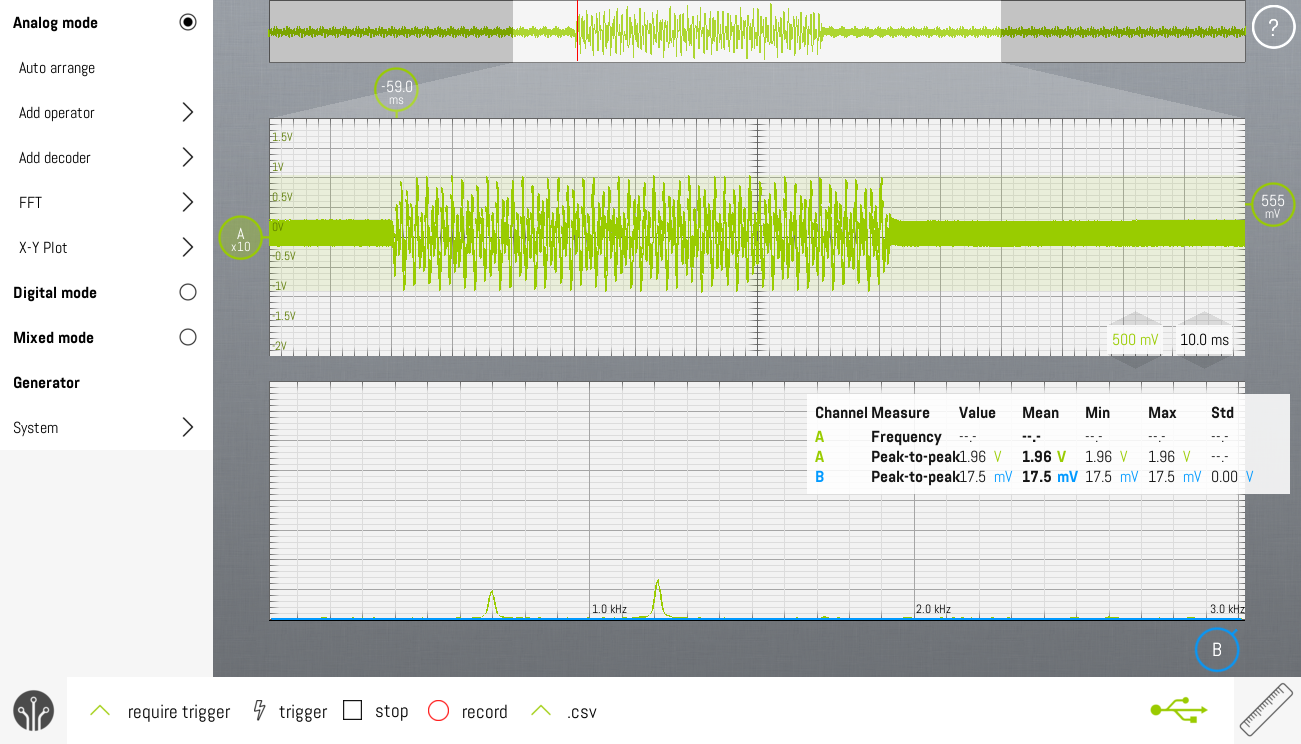
The screenshot shows a screen capture of the SLIC's audio out, while the Philips D200 is dialing "1". The FFT-shows energy on 700Hz (actually 697Hz) and 1200Hz (actually 1209Hz).
- Signal amplitude : 1.8Vpp
- Tone duration : 80ms
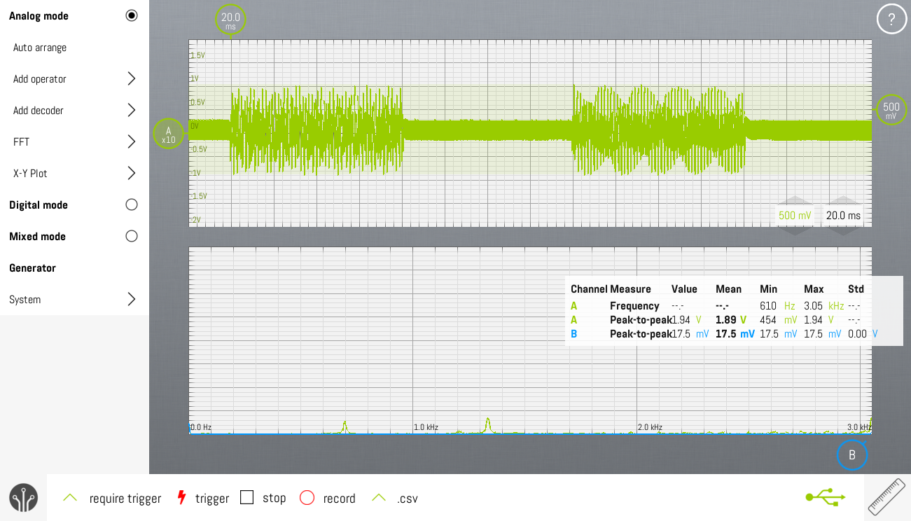
This screenshot is measured on the same signal. This time, the phone is dialing "12".
- Pause duration : 80ms
The SLIC audio conversion relative gain is 0dB, so it doesn't change the amplitude of the audio on the telephone line.
The Philips D200 generates it's DTMF which complies to the standard.
Bbox2 VOIP Box FXS-port measurements
Measurements done with POTS connected.
- On-hook voltage: 47.2V
- Off-hook voltage: 10.0V
Discussions
Become a Hackaday.io Member
Create an account to leave a comment. Already have an account? Log In.