 Dmitry V. Sokolov
Back to the true ternary triador implementation. The ALU will look like this:
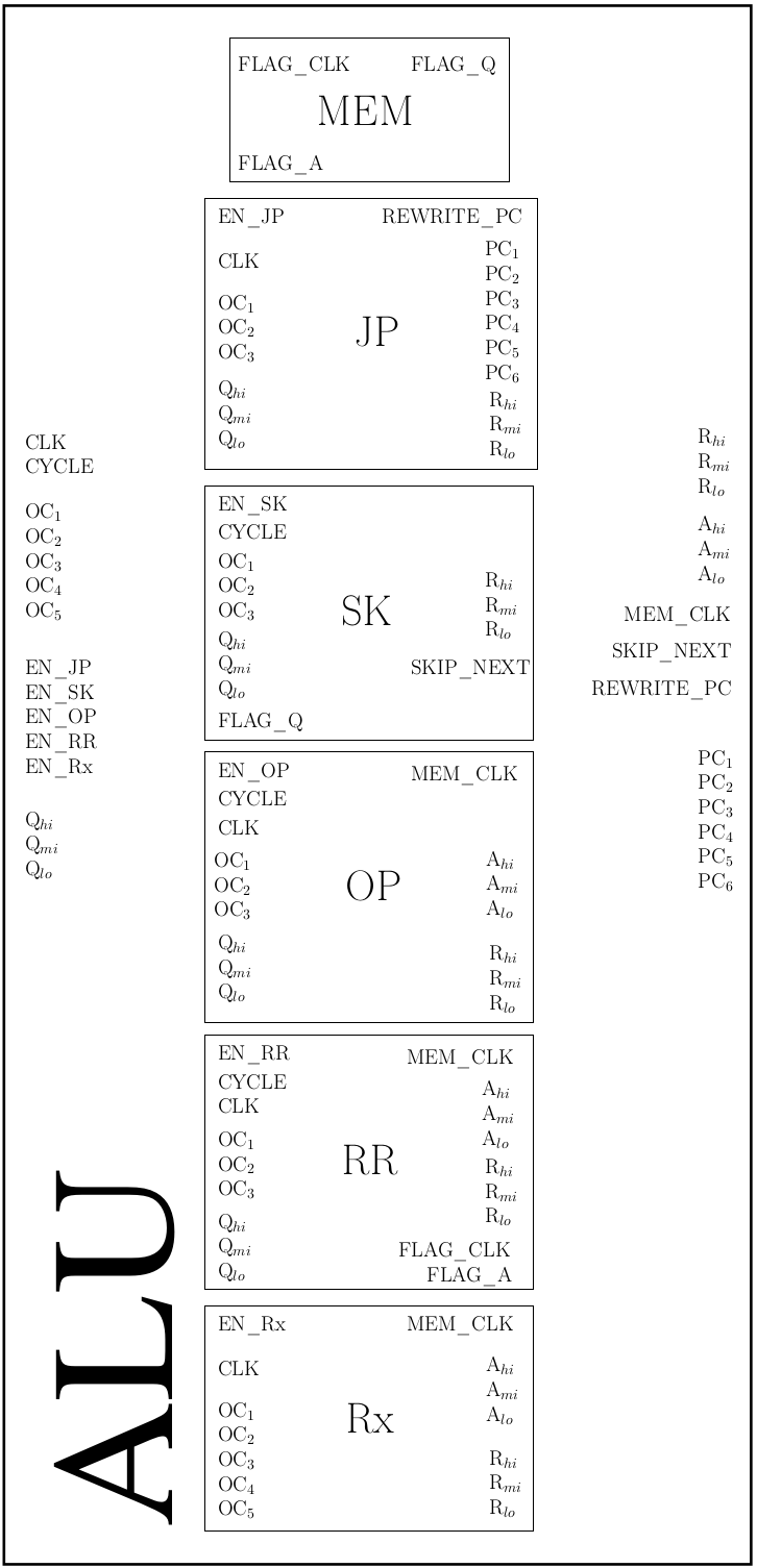
Compare it to the overall schematics of the triador in the project details. All input signals are shown on the left of the boxes, all output signals are on the right. The ALU consists of 5 slices (one per operation) plus one trit memory cell for the borrow/carry flag. This flag won't be accessible outside of the ALU, its value is set by the RR slice, and is read by the SK slice only.
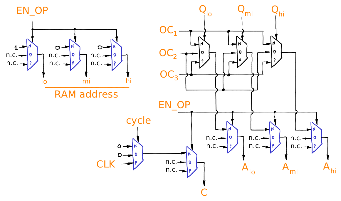
Just to give you an idea of what the boxes look inside, here is the OP box (tritwise unary operation over R1 register):
Discussions
Become a Hackaday.io Member
Create an account to leave a comment. Already have an account? Log In.