 Dmitry V. Sokolov
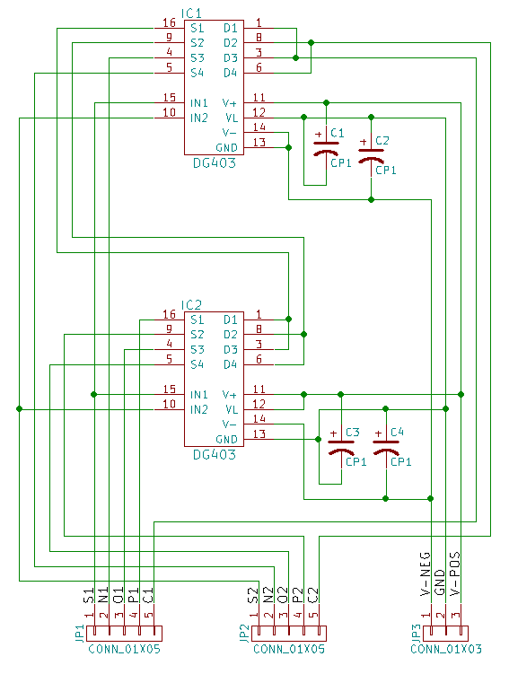
As I said, the only building block allowed is a ternary multiplexer based on DG403 analog switches. With two DG403 it is possible to build a circuit bearing two ternary multiplexers:
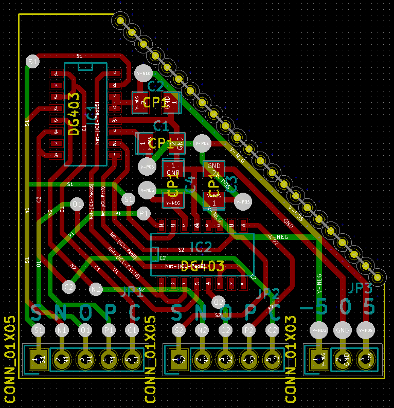
Here is the layout:
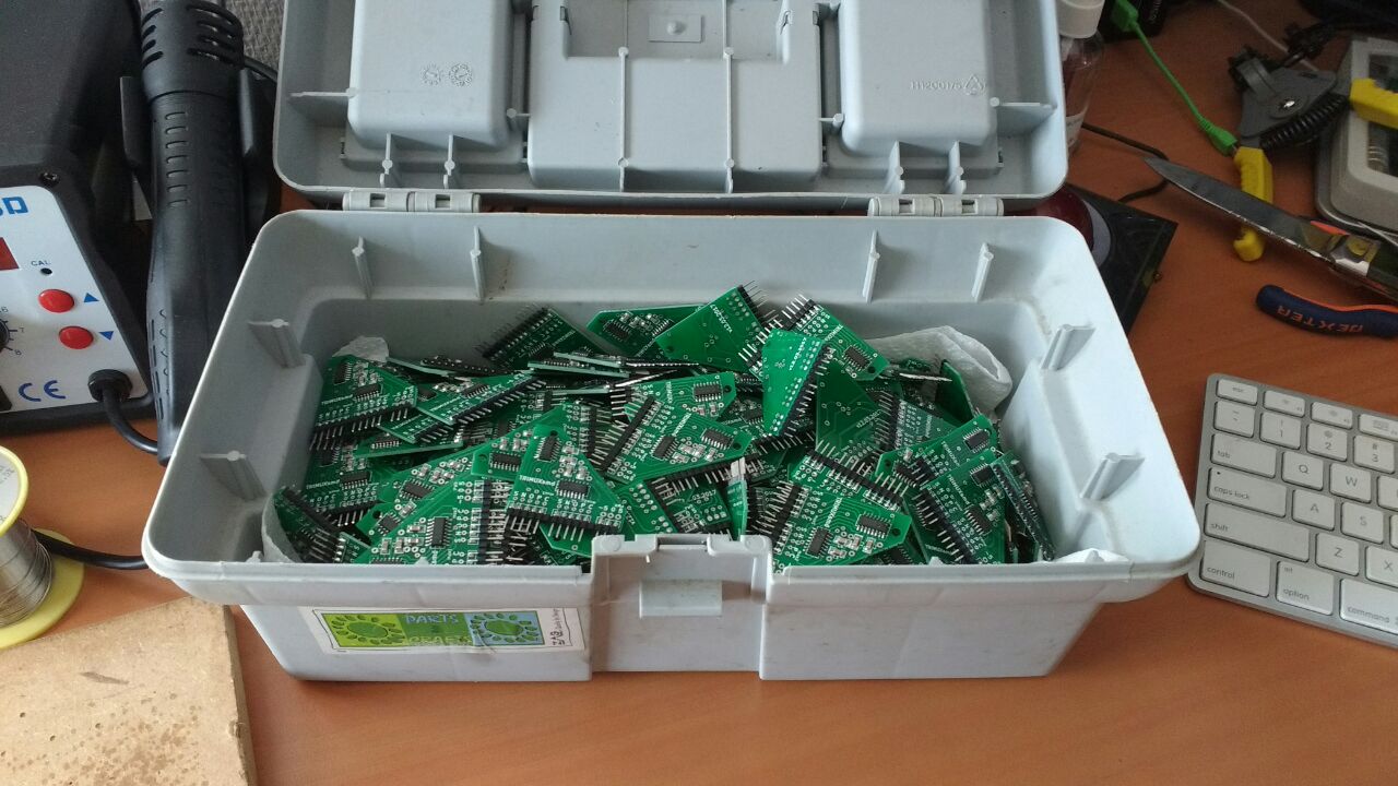
The total budget for this project is set to 300 trimuxes or 600 ternary multiplexers. Here are all the components soldered, cleaned and tested:
Discussions
Become a Hackaday.io Member
Create an account to leave a comment. Already have an account? Log In.
Also original TRIMUX is available on Tindie in form of PCB, KIT or pre-assembled:
https://www.tindie.com/products/TRC/dual-balanced-ternary-multiplexerdemultiplexer/
Note: original TRIMUX has wider space between groups of pins than SMD version described above!
Are you sure? yes | no
This is a link to original TRIMUX on DG403 :)
http://shaos.net/blog/2010/08/ternary-multiplexer-selector.html
I think original drawing is more clearly explaining what is going on over there:
May be I should redraw it to have TERNARY UNIVERSAL UNARY ELEMENT (or "ternary selector") on both sides to match TRIMUX schematics exactly ;)
Are you sure? yes | no