 Dmitry V. Sokolov
On my photos you will often see the FR-2 brown board, I guess it would be good to show how it works.

It has 9 lines that can be used both as input and output, here is the schema of one i/o line:
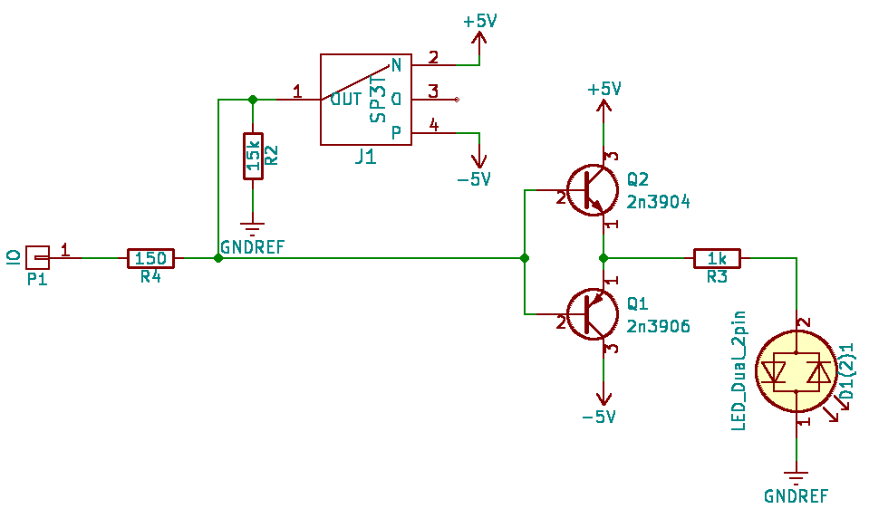
So the board has 9 single pole triple throw slide switches connected to -5, 0 and 5V. When the switch is in the middle position, the line reads voltage. The common collector amplifier is an overkill here.
Here is the layout of the board:

In fact, this is exactly the circuit I have in my program memory, but it can be used for reading signals too.
Discussions
Become a Hackaday.io Member
Create an account to leave a comment. Already have an account? Log In.