 SHAOS
SHAOSNow we will simulate ternary full adder:
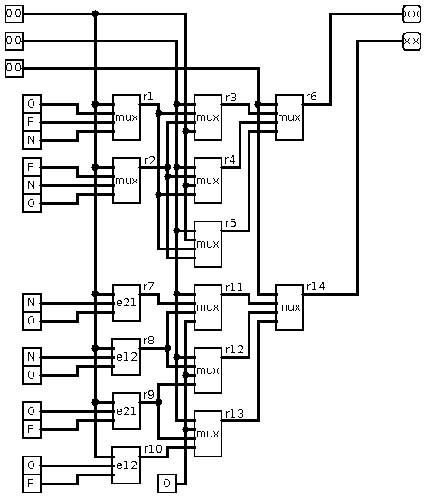
Using ternary.vhd described in previous log, we can do this architecture in VHDL:
use ternary.all;

entity main is
    Port ( a : in FakeTrit;
           b : in FakeTrit;
           c : in FakeTrit;
           s : out FakeTrit;
           c2 : out FakeTrit
             );
end main;

architecture Behavioral of main is
signal r1,r2,r3,r4,r5,r6,r7,r8,r9,r10,r11,r12,r13,r14 : FakeTrit;
signal a1,b1,c1,s1,cc1 : FakeTrit;
begin
process (a,b,c)

FUNCTION io_invert(T: FakeTrit) RETURN FakeTrit IS
begin
                case T is
                when N =>
                        return P;
                when O =>
                        return X;
                when P =>
                        return N;
                when others =>
                        return O;
                end case;
end;

begin

    a1 <= io_invert(a);
    b1 <= io_invert(b);
    c1 <= io_invert(c);

    r1 <= mux(a1,O,P,N);
    r2 <= mux(a1,P,N,O);
    r3 <= mux(b1,r1,r2,a1);
    r4 <= mux(b1,r2,a1,r1);
    r5 <= mux(b1,a1,r1,r2);
    r6 <= mux(c1,r3,r4,r5);
    r7 <= e21(a1,N,O);
    r8 <= e12(a1,N,O);
    r9 <= e21(a1,O,P);
    r10 <= e12(a1,O,P);
    r11 <= mux(b1,r7,r8,O);
    r12 <= mux(b1,r8,O,r9);
    r13 <= mux(b1,O,r9,r10);
    r14 <= mux(c1,r11,r12,r13);
    s1 <= r6;
    cc1 <= r14;

    s <= io_invert(s1);
    c2 <= io_invert(cc1);

end process;

end Behavioral;
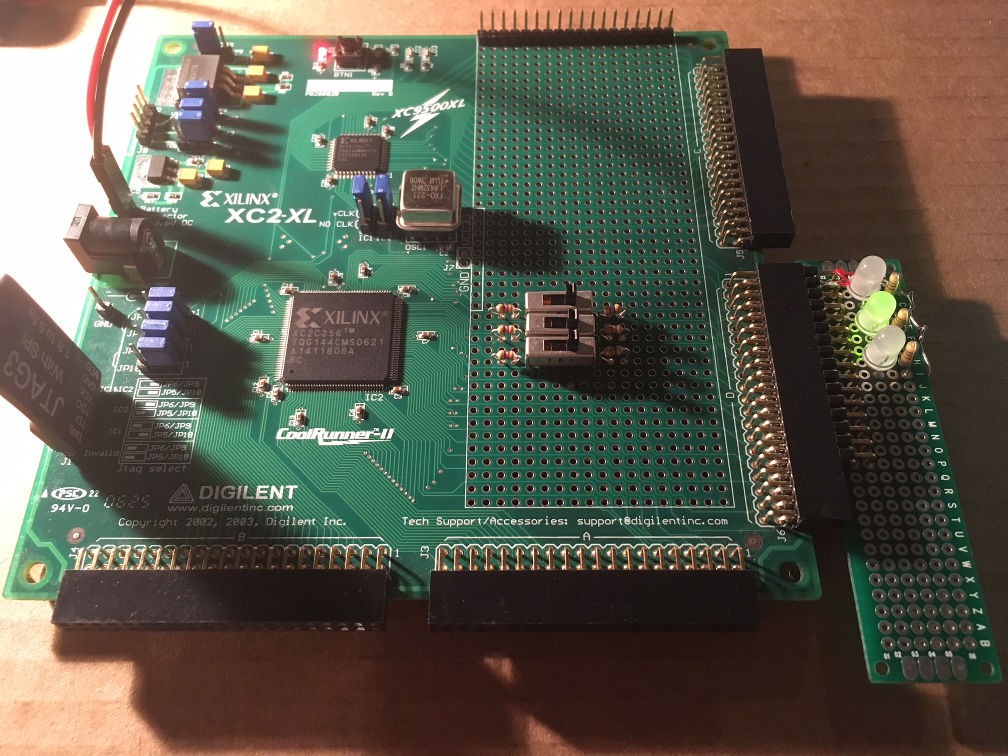
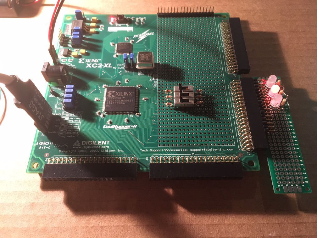
io_invert is function to do bitwise inversion for inputs and outputs, because we are using 3-state switches (0 is active state) and 3-wire Red-Green LEDs (0 is active state) - schematics below repeated 3 time on the board with CoolRunner-II:
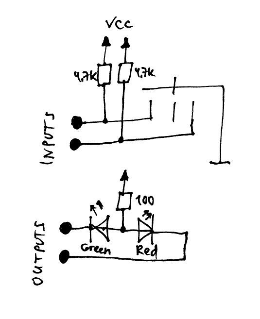
This is 1+1+1 = 3
This is (-1)+(-1)+(-1) = -3
Pin assignments:
NET "a<0>"  LOC = "P140" | IOSTANDARD = LVTTL ;
NET "a<1>"  LOC = "P142" | IOSTANDARD = LVTTL ;
NET "b<0>"  LOC = "P138" | IOSTANDARD = LVTTL ;
NET "b<1>"  LOC = "P139" | IOSTANDARD = LVTTL ;
NET "c<0>"  LOC = "P136" | IOSTANDARD = LVTTL ;
NET "c<1>"  LOC = "P137" | IOSTANDARD = LVTTL ;
NET "s<0>"  LOC = "P87" | IOSTANDARD = LVTTL ;
NET "s<1>"  LOC = "P88" | IOSTANDARD = LVTTL ;
NET "c2<0>"  LOC = "P85" | IOSTANDARD = LVTTL ;
NET "c2<1>"  LOC = "P86" | IOSTANDARD = LVTTL ;
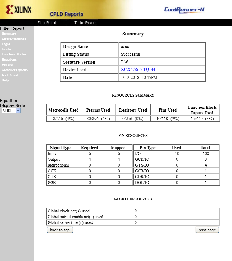
This ternary full adder ate 8 macrocells (4% of XC2C256):
And this is logic equations generated by Xilinx ISE software:

Next step - MEM...
Discussions
Become a Hackaday.io Member
Create an account to leave a comment. Already have an account? Log In.