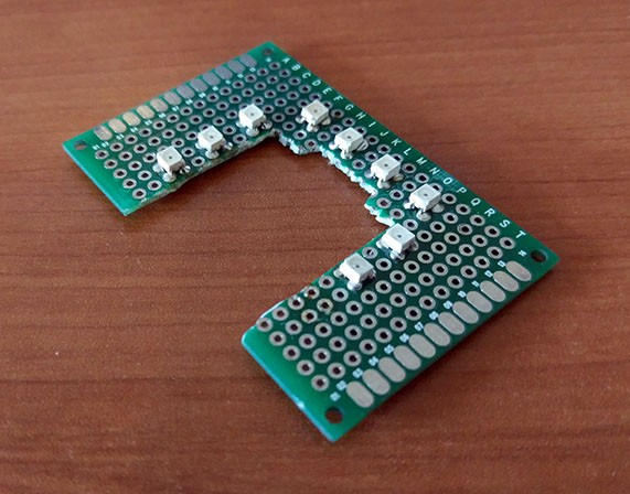
I found some IR LEDs from Digikey that would do the job: 475-1459-1-ND. They are high powered and have a 120 degree field of view, perfect for covering the entire area that can be seen by the camera. I whipped up a quick prototype using the LEDs to verify their effectiveness.

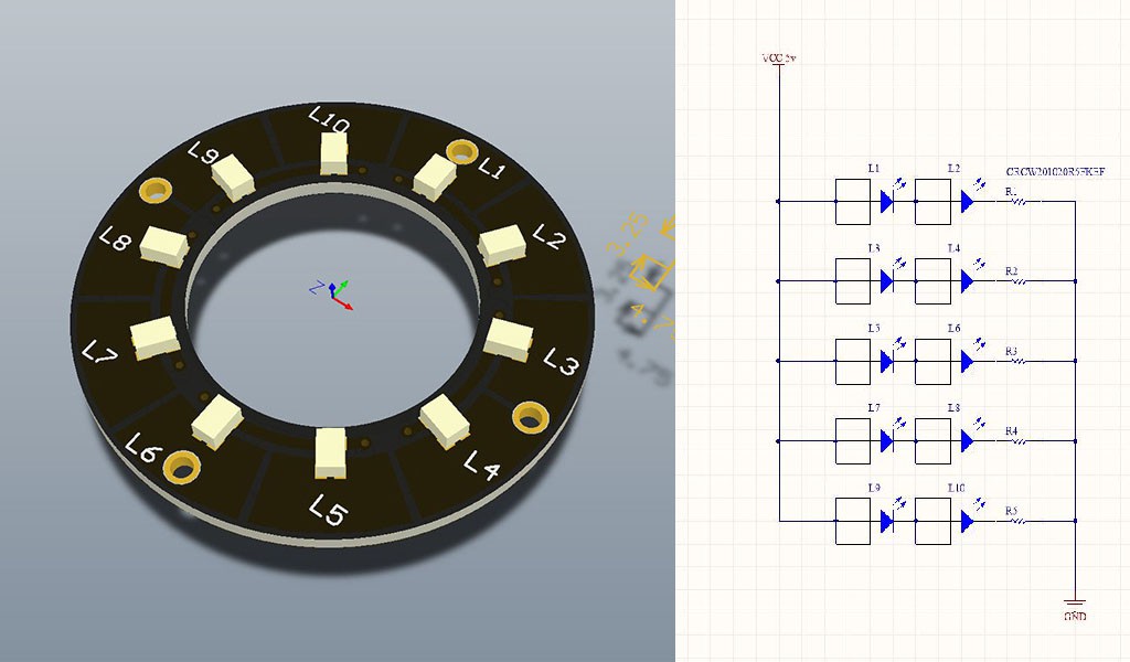
After some research I ended up picking Altiuim's Circuit Maker to layout the PCB. It was fairly easy to use, even for someone with zero PCB design experience, and there is a wealth of information online to help out. I must admit though, I'm a little surprised at how 'clunky' Circuit Maker felt, definitely a much older school take on user interface experience. Nevertheless the first draft of the IR board is done!

It is a very simple LED/resistor network with a connector on the back for the 5V power rail.
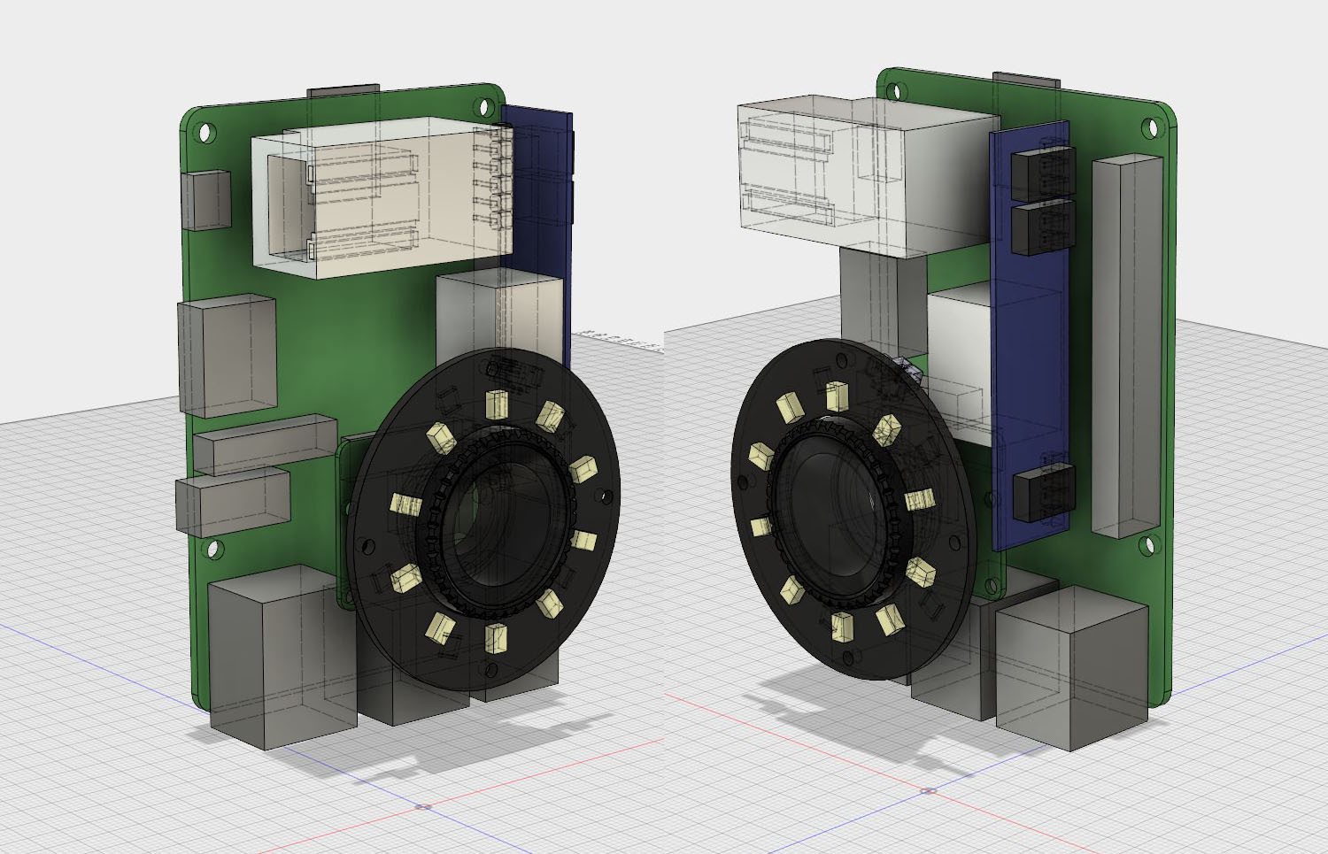
One feature I would love to have for the cameras is power over Ethernet. Only requiring a single cable for data and power is really appealing, especially because a typical setup will require 6+ cameras. After some digging around I found a fairly noob friendly POE module, the PEM1305. It requires very minimal support circuitry and this model can deliver up to 2.59A over 5V. I experimented with the physical arrangement of the components in Fusion 360, not quite sure how everything is going to be held together.

The components in this arrangement are:
- Raspberry Pi 3
- Raspberry Pi camera V2
- 180 degree fisheye lens
- RJ45 Ethernet jack
- PEM1305 power over Ethernet module
- IR LED PCB
 Robert Gowans
Discussions
Become a Hackaday.io Member
Create an account to leave a comment. Already have an account? Log In.