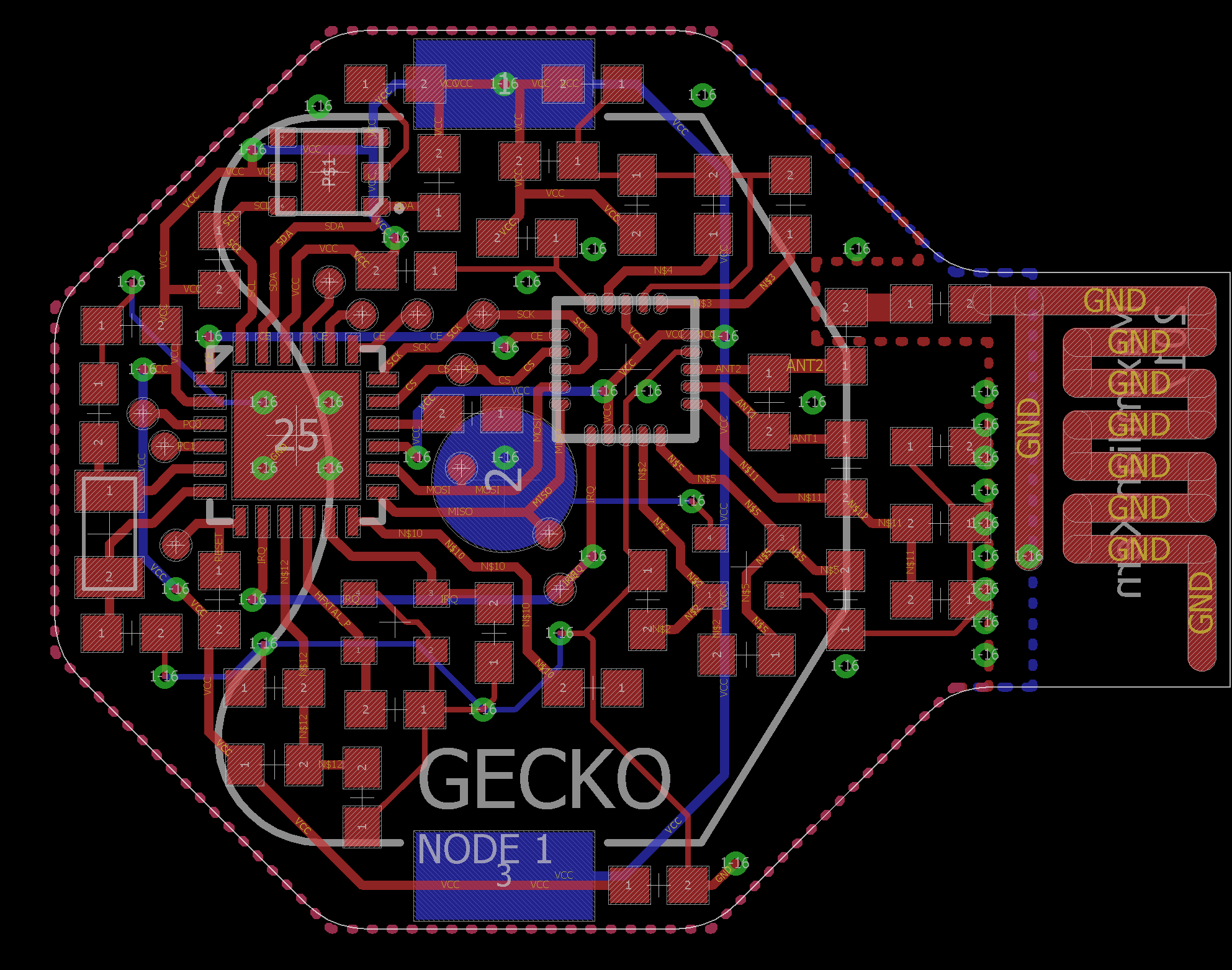
Until now my projects have been restricted to using components that I can solder by hand with a regular soldering iron. This time, I have access to a lab with a hot air rework station. This means that things like the QFN24 Zero Gecko with no visible pins can be soldered. The nrf24l01 also comes in a QFN package and will be soldered on the board directly instead of using its breakout module. The price for these chips starts at around 3€ for single quantities. Instead of ordering them I decided to take apart the breakout boards. Surprisingly these boards cost only 1€ from sites like Banggood (https://www.banggood.com/5Pcs-NRF24L01-SI24R1-2_4G-Wireless-Power-Enhanced-Communication-Receiver-Module-p-1059601.html?rmmds=search&cur_warehouse=CN), while also including the necessary passive components that can be repurposed. Either Shenzhen managed to make perfect clones of the chips or they are buying them at ridiculous quantities.
What's left is the sensor. I chose a hdc1080 from TI, which can measure temperature and humidity at a high accuracy. Its standby current of just 100nA is perfect for this application.
The EFM32, the rf24 and the hdc1080 can all run at 3V. Because of that the entire device can easily be powered by a coin cell. In this case a voltage regulator would only consume more power. The thickness of the device is not that important, so a CR2032 is used.
Here is a quick calculation for the cost of the device (not including the pcb itself):
| Price in single quantity | Price for 1000+ units | |
| EFM32ZG110F32 | 0.91€ | 0.83€ |
| NRF24L01 | 1.86€ | 1.42€ |
| HDC1080 | 2.43€ | 1.25€ |
| Oscillators etc. | ~3€ | ~1.50€ |
| 8.20€ | 5€ |
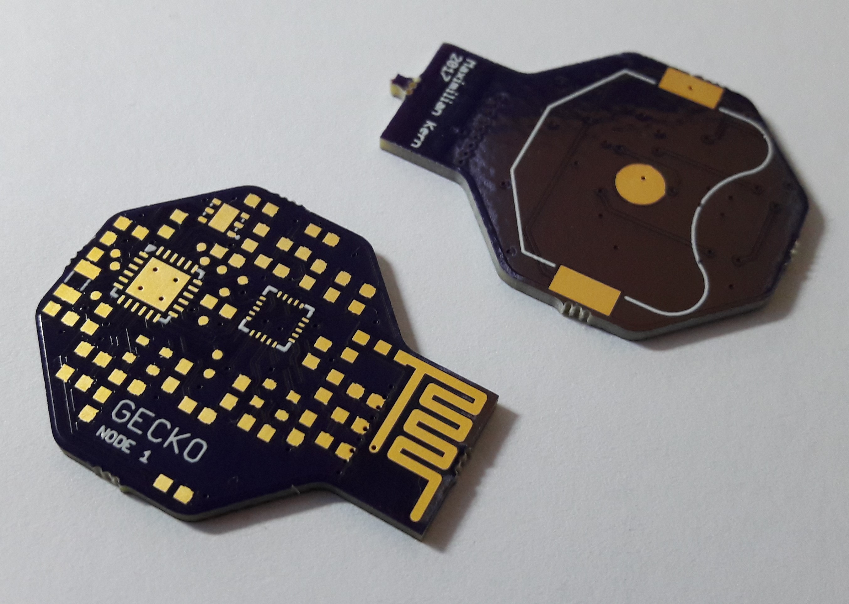
The size of the PCB is mostly limited by the coin cell holder, which is the widest part. I would have liked to make the board circular, but the antenna needs some space as well. I decided to copy the copper layer antenna that the rf24 modules uses. This way no additional components are required.

The PCBs were ordered from OSH Park and, as usual, all three are perfect apart from my own design flaws, which I'll get to later.

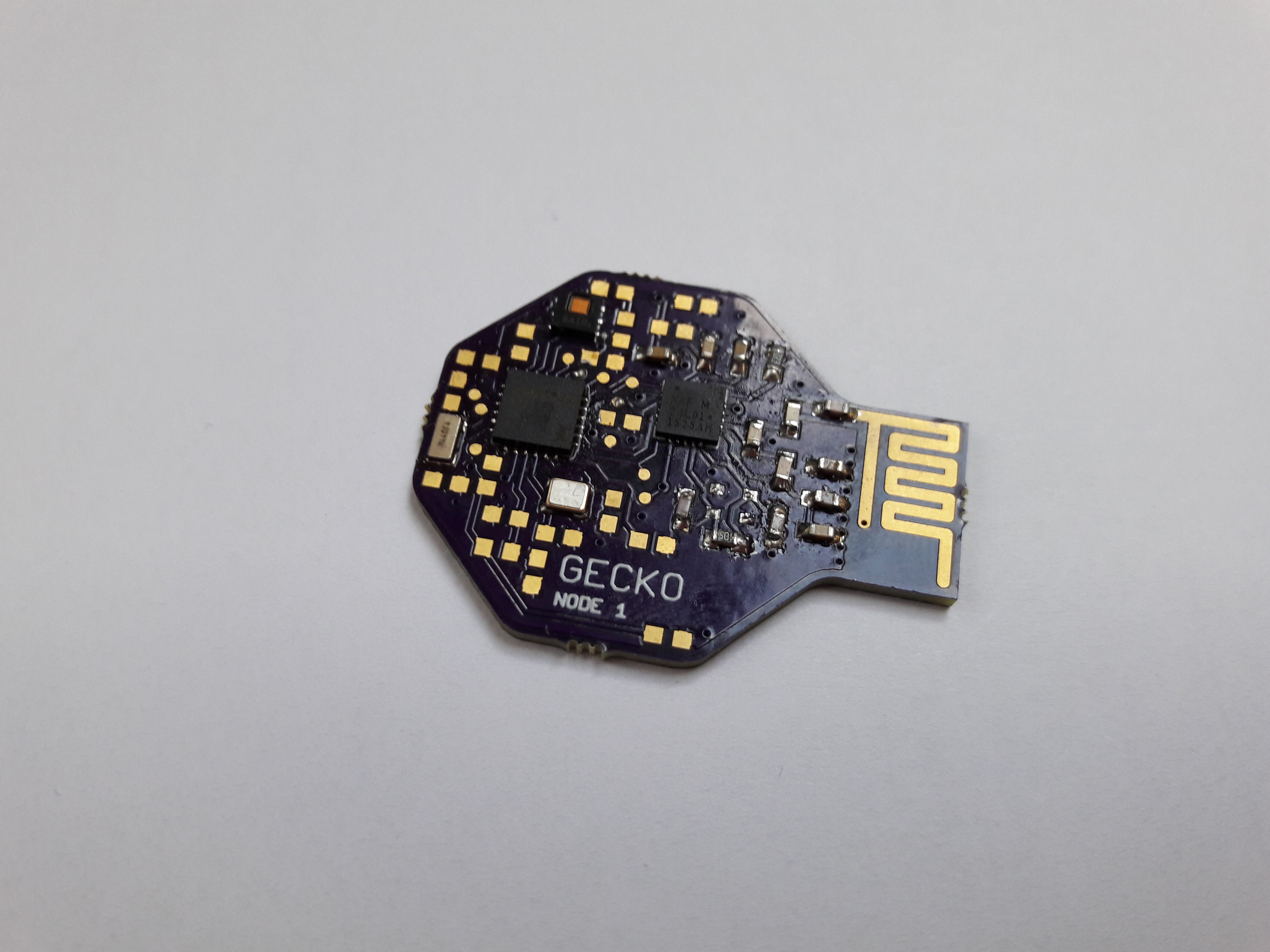
For me, this was my first time working with a hot air station. To add another level of difficulty there was no solder paste at hand, which meant that regular solder had to be applied to the pins. Fortunately, most components are very forgiving when it comes to high temperatures. I botched the first of the three PCBs which meant that it was fully working in the end but the rf24 was drawing more power than it should. I will have to increase the size of the pads for the ICs in the next revision.
Getting the nrf24l01 off the breakout board and onto the new pcb was fairly easy. It is important not to confuse the three different inductors on the board, because at only a few nH they are difficult to measure.

 Max.K
Max.K
Discussions
Become a Hackaday.io Member
Create an account to leave a comment. Already have an account? Log In.