Detail Description
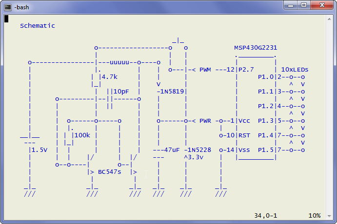
- A joule thief circuit is used to step up the voltage from the 1.5V button cell to power the microcontrollers and leds.
- A push button instead of a switch is used to complete the joule thief circuit.
- Initial push button depress starts the joule thief and supply start up voltage to the microcontroller (which operates at 1.8V to 3.6V).
- A zener diode limits the maximum voltage to 3.3V. This can be replaced by a 3.6V zener if higher voltage is needed
- Once the microcontroller boots up, and the push button releases, the microcontroller takes control of the joule thief.
- Microcontroller samples the supply voltage via internal ADC and switch on the joule thief (mimicking a push button depress) when voltage is less than 3.2V and switch it off when voltage is below 3.2V. This provide certain efficiency benefits to the otherwise inefficient joule thief circuit. The voltage threshold can be altered via source code change.
- The led christmas tree cycles in a fixed lighting sequence.
- There are 4 + 1 different display modes; breathing, solid, throbing, and twinkle, plus an automatic cycling of the four modes.
- The display starts w/ a breathing display mode when initially turned on, and cycles between the above-mentioned 4+1 modes upon keypress.
- The same I/O pin is used for switching the joule thief and for push button reading. The firmware switches the I/O pin periodically to input and reads the button state.
- A long keypress will shut-down the display via switching off the joule thief, leading to collapse of the voltage supplying to the microcontroller.
- The entire build incluing power is on a 170 tie-point mini breadbroad.
- This project demonstrates an switching joule thief design, timers and interrupts, analog digital conversion usage, and LED multiplexing / charlieplexing.
Application Notes
- Single button press turns on led tree
- Subsequent single button press (indicate by top led on) rotates these display modes; breathing, solid, throbing, and twinkle, and cycling
- Long press (indicate by 2 led on) turns off led tree
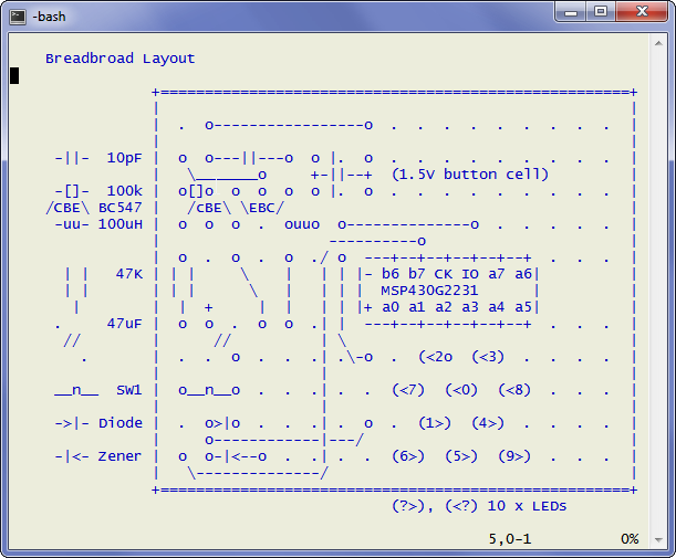
Breadbroad Layout
Schematic
Assembling
- Follow breadboard layout and place jumper wire on mini breadboard
- Place joule thief components with larger components go first
- Place MSP430G2231 on breadboard
- Cut your LEDs into different lengths, *be sure to maintain one leg longer
- The top most LED need extra long legs via soldering cut legs from a sibling
- Place LEDs accordingly, you can substitute different color LEDs that works up to 3.2V
- Battery Holder was made by reshaping pins in a double row male pin header section
Parts / Bill of Materials
This is what's needed for this project
1 x MSP430G2311 (can be substitute by MSP430F2012
1 x 170 tie-point mini breadboard
1 x 4.7k, 1 x 100k resistors
1 x 10pF ceramic capacitor
1 x 47uF electrolytic capacitor
1 x 100uH inductor
2 x BC547 or any small signal NPN transistor
1 x 1N5819 or similar schottly diode
1 x 1N5228 or any 3.3V zener diode (500mW)
1 x tactile switch
Jumper wires
Double row male pin header to be used for battery holder
1 x LR44 1.5V coin cell battery
 Chris Chung
 Yann Guidon / YGDES
 Steph
Steph
 Jeroen Brinkman
One of my favorite prototyping tricks is to use the pin headers as a breadboard coin cell holder. I've only done it with the CR2032 but glad to see you using it for the LR44. I'm going to keep that in mind for future projects.
Great build!