The Boxer-1 uses instructions that look like:
[4-bit Opcode] [8-bit Data]
Registers A and B are each 8-bits. These are general purpose registers that are used for the Adder/Subtractor as well as general writing and reading to ram. They only effect the 8-bit data space.
Register C is 12 bits long. This allows for entry of opcodes into ram. This register is put into effect by using a 4-bit Binary Counter, an Inverter, and a Nand gate to create a ring counter. I ended up using these chips just because they are available. Data is entered 4-bits at a time to the register. Three "Load C" instructions complete the write.
I am still learning about computer architecture and from what I understand having a 12-bit register on an 8-bit computer is unusual. To the best of my knowledge it is the best way to take full advantage of the 8-bit address bus.
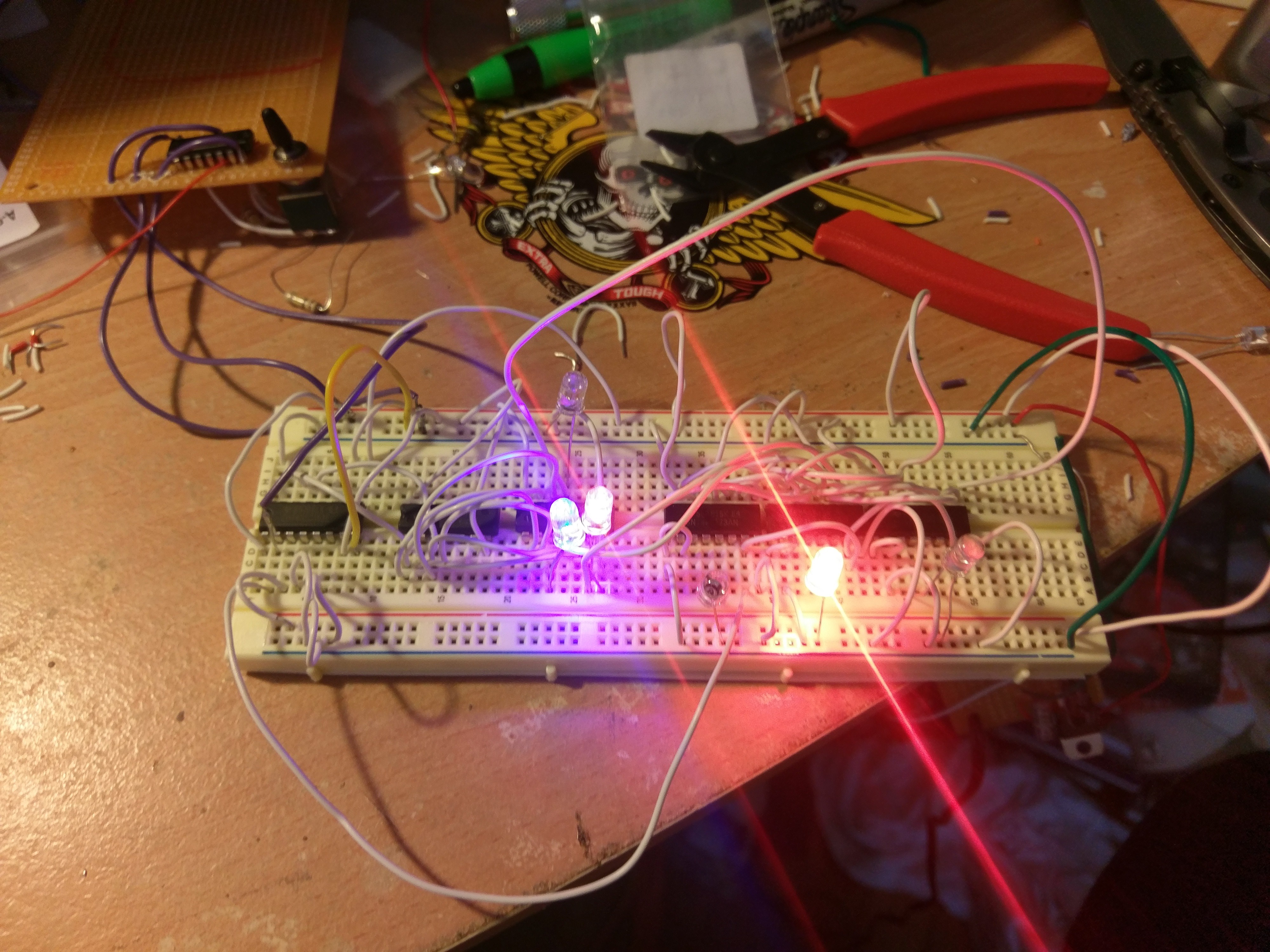
Attached is my first attempt at building this register. It still uses a single step clock source so I have no idea how to will preform at a higher clock rate. I might have to add a falling edge clock circuit.

 Boxerbomb
Discussions
Become a Hackaday.io Member
Create an account to leave a comment. Already have an account? Log In.