lion mclionhead
-
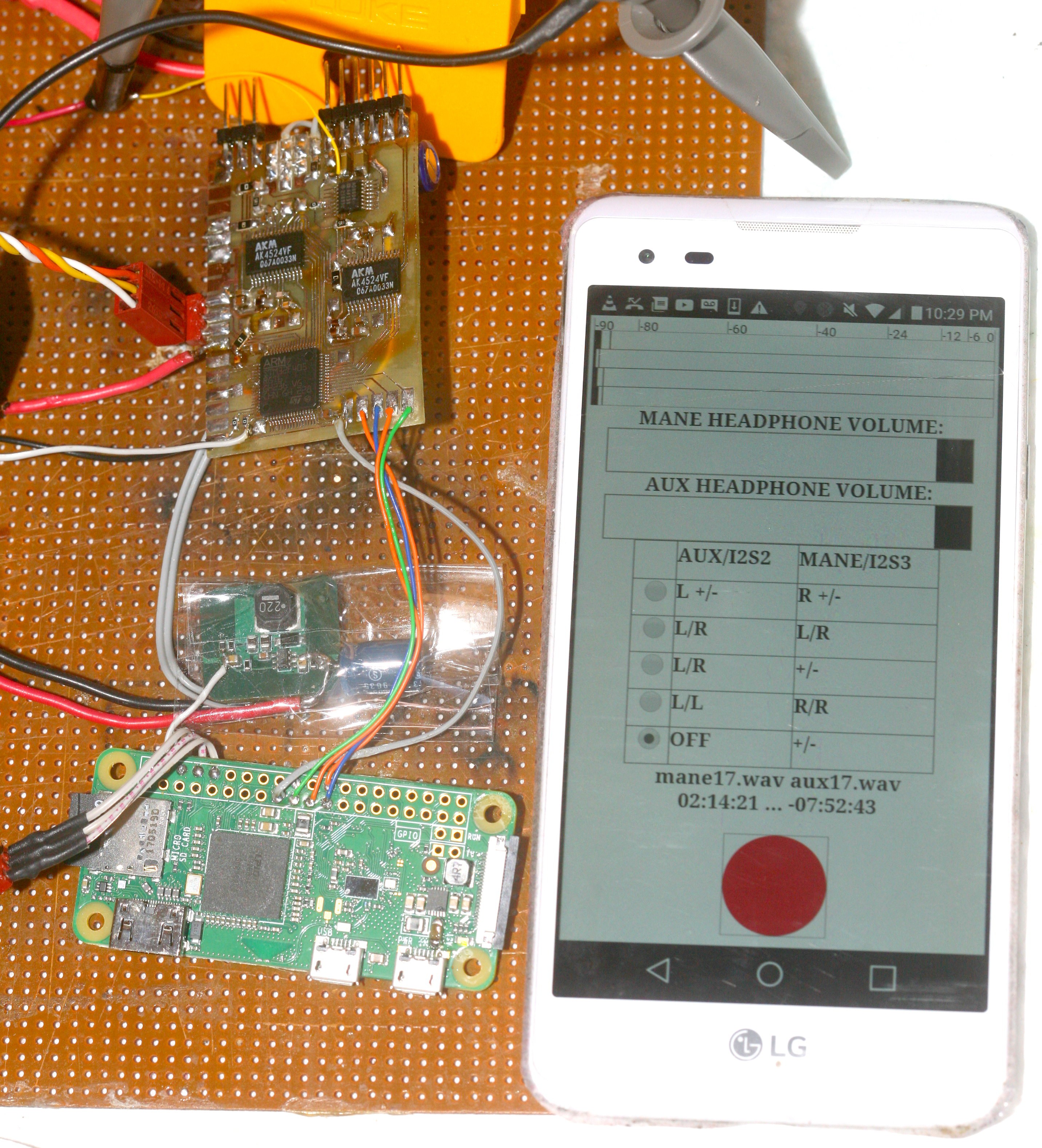
The GUI
01/15/2018 at 07:37 • 0 comments![]()
The mane feature of the GUI is the setting for mixing the 4 ADC's. Mixing down before writing was deemed necessary, since the storage goes from 10 hours for a single channel to 2 hours for 4 channels & multiple files with differential pairs are a pain. The mixing for storage is a completely different set of equations from the mixing for monitoring.
The VU meters still show the independent levels of the 4 ADCs. The top 2 are the AUX I2S & the bottom 2 are the mane I2S. The board layout led to the mane I2S always being the higher number on every list.
The 2 monitoring volumes are applied differently, depending on the mixing formula. The easiest way to figure out how they're mixed is by listening & tweeking the faders.
The mane trend is the use of the ADCs in the AK4524 as either a differential pair, an averaged pair, or 2 discrete channels. It should be obvious from the GUI. Each I2S needs to write to its own file because of synchronization problems. The Zoom H2 had the same problem.
After a heroic programming session, the file writer was upgraded to a 16 second buffer which writes as soon as it has data instead of in 1 second chunks. The SPI buffer was increased to 1/18 second, which was the maximum the STM32 could easily fit. More draconian measures could get it to 1/11. Unfortunately, its core coupled memory isn't accessible to DMA, which would have doubled the SPI buffer.
With all that going for it, it still overran once when recording 4 channels for 40 minutes. Don't expect to ever record 4 channels, except for testing the other modes. The next step would be recording to USB storage or moving the whole PI to a faster SD card.
It still only does 48khz & only uses the AK4524 as the source for I2S2. Have never ever used 96khz, despite it being on the Zoom H2. The biggest value was 24 bits. The problem is moving the ultimate stereo amplifier to a commercial 96khz DAC would give up the external tap for I2S. It would be a matter of swapping the TOSLINK between 1 board purely for capturing it & a board for listening to it or somehow splitting the TOSLINK. A USB soundcard would be the hardest to sniff.
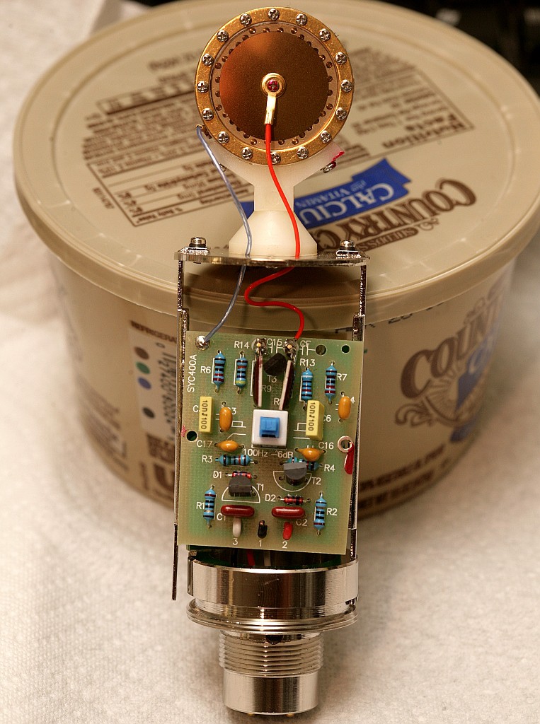
The next matter is the preamp.
![]()
The thought occurred of dumping 48V phantom power & replacing the microphone electronics with op-amps boosting directly to line level. These mics are virtually free, have been replaced by USB versions & it would reduce the noise. It would require exposing some kind of gain adjustment, but the metal enclosure is absolutely required to stop interference. It's not for stopping singers from accessing the bass rolloff switch. A preamp conversion would be a lot of work splitting mane hairs for a truly meaningless difference.
-
1st recording
01/14/2018 at 07:18 • 0 commentsCapturing PC audio in software sounds like a good idea until you have to monitor the PC audio in the phones. That would require a mixing board & a bunch of wires. The easiest way is capturing TOSLINK on the same board as the microphone & mixing it in software. Sometimes, the best way to do more in software is more custom hardware.
The trick is the AUX I2S clock is going to drift away from the mane I2S or be at a totally different sample rate. The only solution is to record different files for each I2S & take nearest neighbor samples for the monitoring.
Otherwise, rediscovered the raspberry pi's largest SPI buffer is 4096 bytes. You need to add spidev.bufsiz=32768 to /boot/cmdline.txt to expand it.
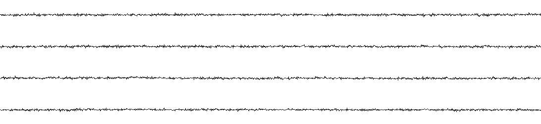
The 1st audio file recorded open circuits & showed -86.6, -87.6, -87.4, -88.08 dB for the maximums & -99.4, -99.8, -99.8, -100 dB for the RMS. They strangely got quieter as they went down the board, but were all good enough.
![]()
4 channels magnified to 1/262144 per Y.
When recording different files for the 2 I2S streams, it overruns all the time, even at 48khz. CPU usage is 5%. In typical ext4 fashion, it frequently locks up while doing an extended write. Mutex locking the 2 file writers doesn't help. The maximum SPI buffer size which can fit in the ARM is 12296 bytes. It needs some minimal mixing instead of writing the full ADC output & a more optimized buffer algorithm. Partitioning the flash into a raw area might be required.
The 1st files it recorded before it crashed:
-
I2S & DAC testing
01/12/2018 at 08:38 • 0 commentsIn testing the DAC, the single ended output voltage is roughly 1.1 - 3.9 with the center at 2.5. The DAC is 20 bits, so you need to write -0x80000 to 0x7ffff. The ARM was configured with I2S_Standard = I2S_Standard_MSB, I2S_DataFormat = I2S_DataFormat_32b, I2S_CPOL = I2S_CPOL_Low. The AK4524 was configured with I2S mode 1. The I2S->DR register is written as well as read with most significant 16 bits 1st. The ADC spits out the sample left justified & the DAC takes it in right justified. In 96khz mode, the AK4524 drives I2S at twice the bit clock as 48khz mode but the format is the same.
Unfortunately, to minimize noise on the 5V rail, the headphone amplifier is powered by the 3.3V rail & it's DC coupled to the DAC. At least for the 440Hz test tone, the AD8604 dumps loads of current & 100% volume is far too loud. 50% volume is required to get below 3.3V & that is also quite loud. May just risk using the 5V rail rather than make an AC coupled headphone amplifier. Other ideas are shifting the midpoint in software to 2.2V, giving roughly 75% volume. The output does seem to be DC coupled to the DAC. It also has an intermittent problem of not initializing the left DAC after an ARM reboot until being power cycled.
Didn't notice any noise with the 3.3V power. Differential output definitely isn't necessary for a simple headphone monitor.
-
Board bringup & full duplex I2S
01/11/2018 at 09:27 • 0 commentsOnce the usual GPIO snafus were fixed, attention turned to using the AK4524's built in DAC for monitoring. Banging on this discontinued chip isn't so bad when you consider guys are going around building computers out of 6502's.
C11 didn't work as I2S3ext_SD. Only B4 did. The datasheet had a buried nugget about aux function GPIO_AF_I2S3ext having to be selected for C11 while the aux function was GPIO_AF_SPI3 for B4. No amount of register banging could send data out of C11. What did help was printing the contents of SPI3->I2SCFGR & I2S3ext->I2SCFGR to verify the key registers were being set correctly. Also review the I2S_FullDuplexConfig, I2S_Init functions. Once full duplex is enabled, you have to use I2S3ext registers to send or receive data using the ext_SD pin & the I2S3 registers to access the SD pin. Both pins can be inputs or outputs.
The timing of when to send what 16 bits to the DR register to reconstruct 2 channel 24 bit samples is a bit tricky. Similar to a state machine which uses the channel side bit & a counter to sort the 16 bit reads from the DR register, another state machine must use the same bits to sort 16 bit writes. Not sure how people do it with DMA, but it definitely must be done with polling to downmix the 4 input channels & monitor audio without latency.
-
PI assembly
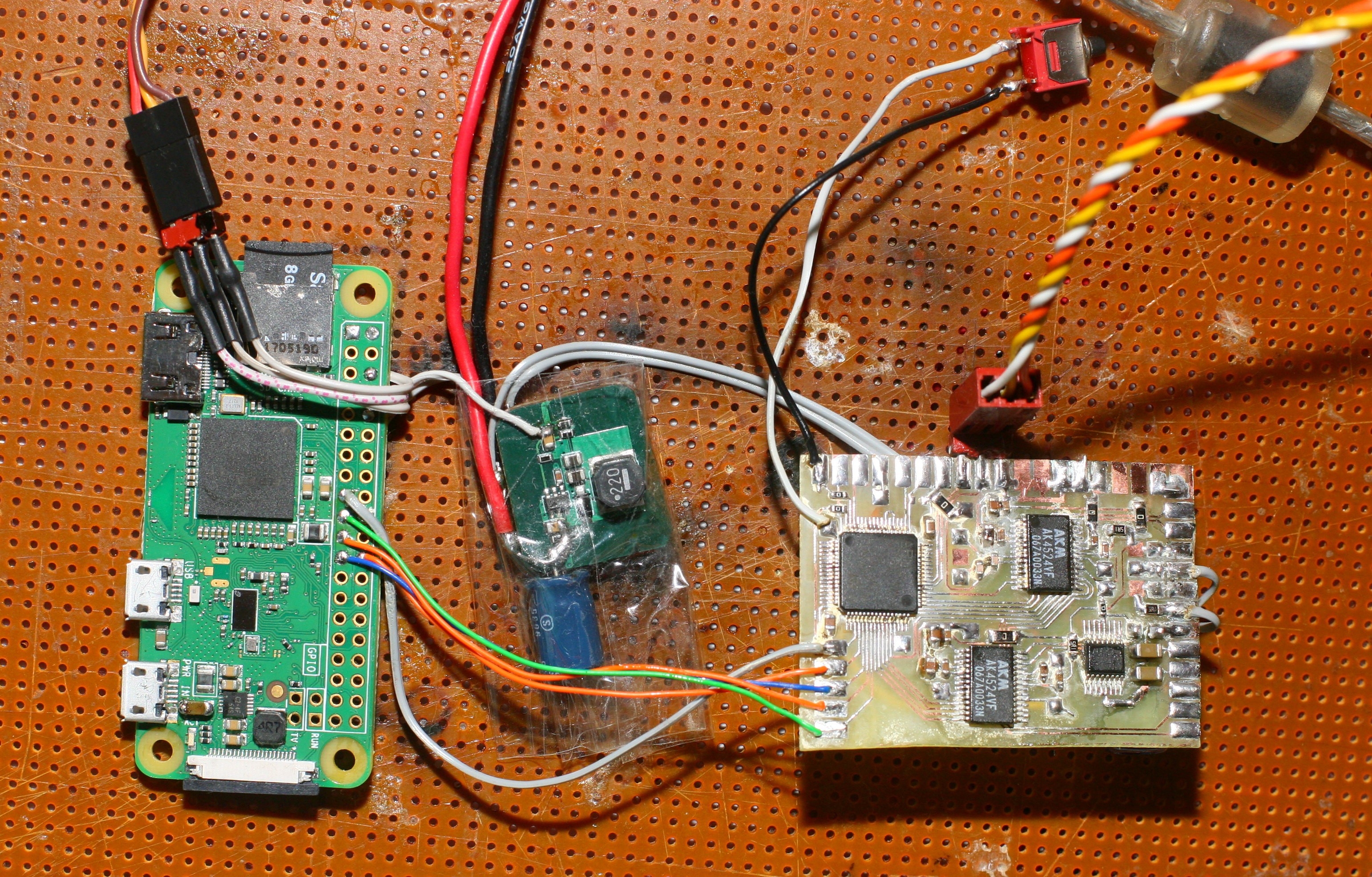
01/10/2018 at 19:43 • 0 comments![]()
It was disappointing to find that the ARM was bad. VCAP went only to 0.5V & it wouldn't boot. Shorting it to VDD got it to start. Reflowing it a few times got it to 1.2V but it still wouldn't boot. Hopefully, it was a solder ball, but the ARM was replaced with a working chip. It's a big deal when an STM32F4 dies because they're still $10 a piece, to this day. A whole raspberry pi is less, but it doesn't have triple I2S ports.
The complete PI section was attached. Another high voltage lead is required for the preamp. The 24 bit vlogging mic was cannibalized.
-
1st board
01/09/2018 at 05:57 • 0 commentsThe 1st analog board came together, in its test harness. It's not as ambitious as some past quad copter boards, but presents challenges in signal quality. Made every effort to star ground the analog grounds, separate the analog grounds from the digital grounds & copy the 5V filtering discovered on the single channel board. Although it still has an extra I2S port, decided it would be better to develop something in software using Jack to record the computer than capture the TOSLINK output.
-
Still laying out
01/03/2018 at 19:34 • 0 commentsTo save money on clothing, the decision was made to etch the Zoom replacement & the additional board for the ultimate vlogging mic on the same day. The zoom replacement undergoes continual evolution like everything else.
![]()
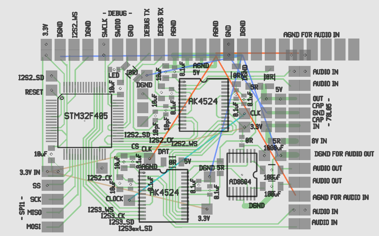
but converges on a mane ADC board which attaches to interchangeable front ends. The mane board exposes its spare I2S pins for an arbitrary I2S source. The lower ADC also provides a DAC for monitoring, so it's always connected & has to be the one taking input from any 2 channel front end. The upper ADC has to share its I2S pins with the aux input. They're obsolete ADC's, but easy & good enough. Digital & analog grounds were carefully starred.
The PI connects on the left. The front end connects on the right. The whole thing takes only 1.5" x 2", manely because of cost. Fully equipped with a front end, battery, & PI, it should be much smaller than a Zoom.
The 5V regulator is a pain. Need to test the impact of 5V power supply on the noise, again. The answer is FUGGEDABOUTIT. You can't use the PI's 5V for audio. The AK4524 actually drops its 5V to 3V internally. Its DAC is centered on 1.5V & the ADC is centered on 1V, but no further testing of the ranges was done. The theory behind powering the op-amp headphone driver off the digital 3.3V was the DAC only going from 0-3V. This would be much better off the 5V analog, but need to test the impact on the ADC.
It needs a dual balanced mic front end. Someday, it'll have a dual, unbalanced electret front end & a quad line input. The front ends are going to need their own microcontrollers, have a single UART wire for controlling pots, 3.3V digital, digital ground or just use analog pots & skip all that. They'll need 5V analog voltage & analog ground.The audio inputs are wired to be balanced pairs. To use them without balancing, just leave 1 disconnected. Each goes to its own ADC with the summing in software.
It took a while to realize that all the STM32's can be programmed with just 2 wire "SWD" instead of the full JTAG port. This nugget came from tearing down a brushless gimbal & already having discovered the SWD mode inside an NRF51 dev kit. It saves immensely on board space.
Ultimate 4 channel audio recorder
Portable, 2 channel, balanced input, 24 bit 96khz recording