Close
0%
0%

Low power IR beacon

A battery powered, periodic infrared beacon for a geocaching puzzle

Similar projects worth following
The goal of this project is to build a battery powered IR beacon that will be periodically transmitting a number. It will be used as a virtual geocache.

Motivation

This project starts as an entry for the Coin Cell Challenge, but I hope it will outlive it.
I enjoy microcontroller projects and geocaching. Let's make something that will be fun not only for me, but also for others!

Goal

The basic idea is to make a beacon that periodically transmits a number. This number will be used a password for a virtual geocache.

The device should be small and easy to hide. It should last a year on a single battery. The battery must be replaceable. It will be placed outside, so it must be weather-resistant (rain, snow, ice, direct sunlight, temperatures -20°C to +60°C). Transmission must have a broadcast range of at least 20m  (up to 50m if possible). It should follow a well documented protocol. The number should be hard to guess and contain a checksum.

Construction of a receiver will be left to the geocacher, but example code and schematic should be included

  • 1 × ATtiny13A Microprocessors, Microcontrollers, DSPs / ARM, RISC-Based Microcontrollers
  • 1 × CR2032 Batteries and Battery Accessories / Batteries
  • 1 × IR LED

  • Power source woes

    piotrb5e301/05/2018 at 23:47 0 comments

    After some testing I conclude that a cr2032 is not a good choice for powering this project. A really large rail capacitance would be required to get a high enough current through the LED over the duration of the transmission. The losses on capacitor leakage would be unacceptable.

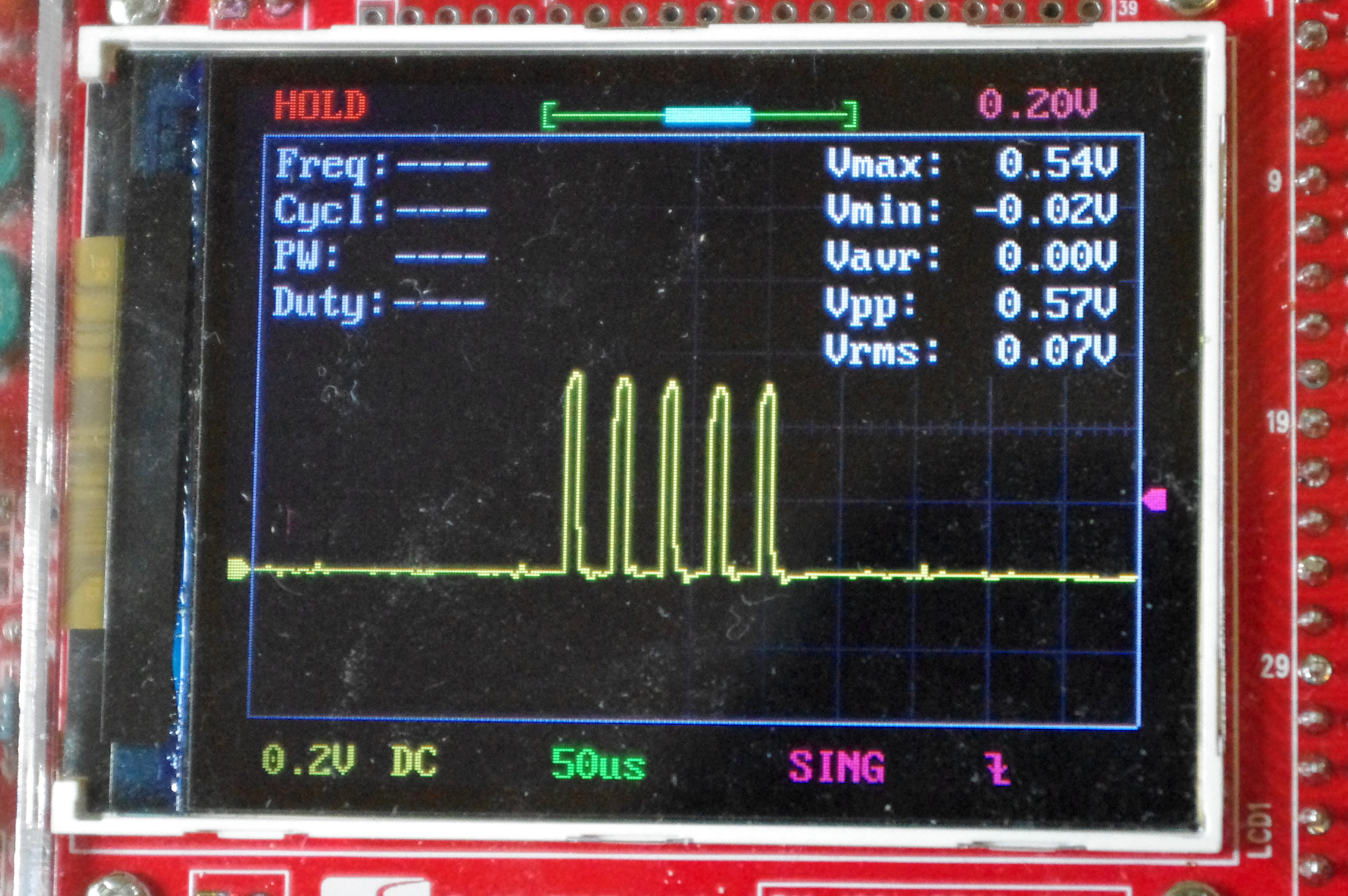
    Voltage measured over a 1Ω resistor in series with the LED. The first few pulses measure at around 500mA - just as planned.

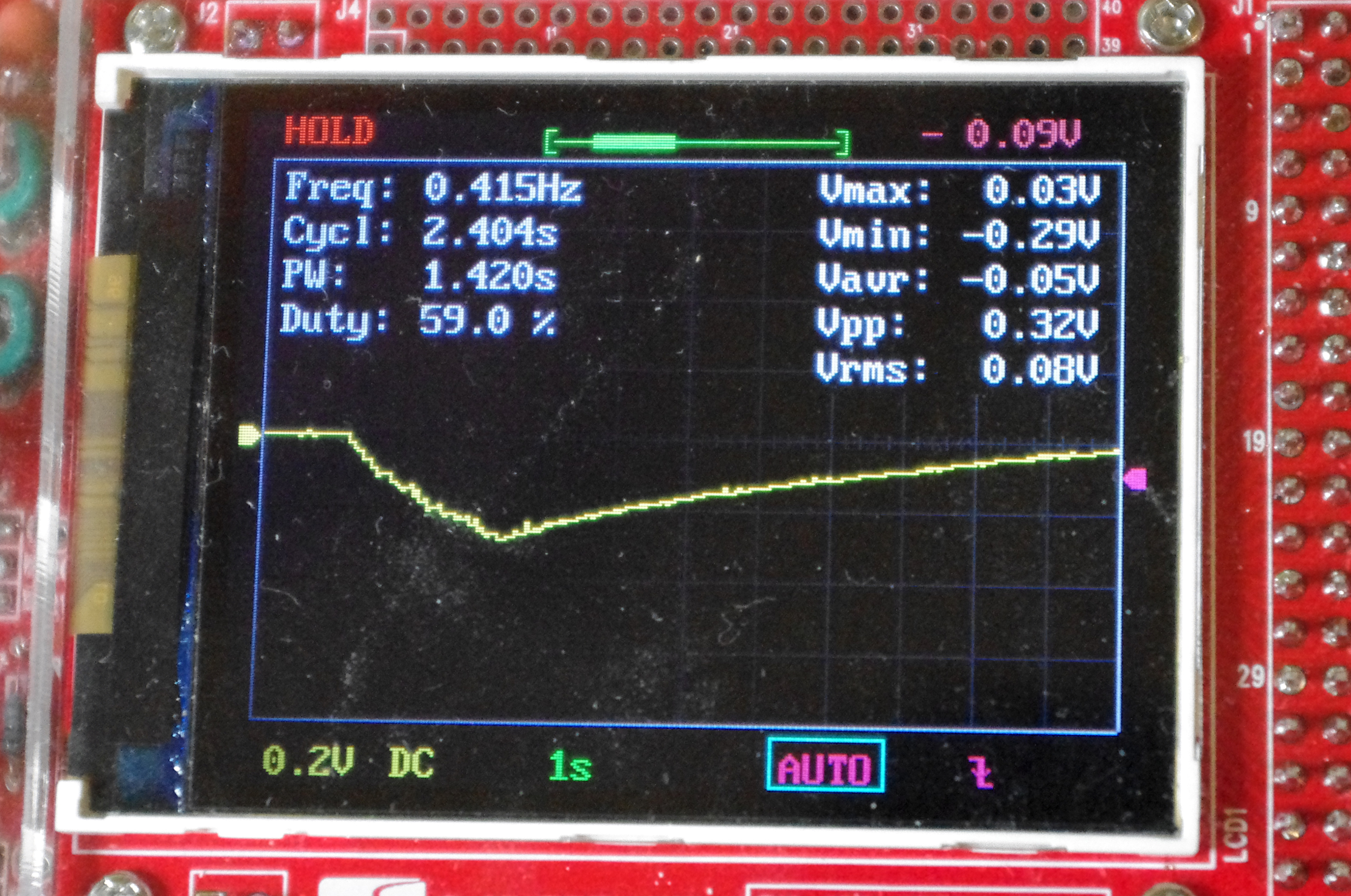
    Unfortunately, even 800μF worth of caps wasn't enough to prevent the rail sag.

    The 300mV drop on the power rail corresponds to a 300mA lower current through the LED. The last few pulses are delivered at just 200mA. The range from which the message can be read clearly is around 10 meters, and requires pointing the receiver directly at the transmitter.

    And that's with delays between pulse trains increased twofold, halved pulse train length, and carrier duty cycle of 25%.

    I think that either 2 LR03's, or 3 NiMH 40H's with small solar panels will have to be used in this project.

  • Going green

    piotrb5e301/04/2018 at 00:00 0 comments

    NO CR2032s WERE HARMED DURING THE FILMING OF THIS EPISODE. THE TL431 GOT SICK AND SOMEBODY LOST A CAPACITOR BUT THAT'S ABOUT IT.

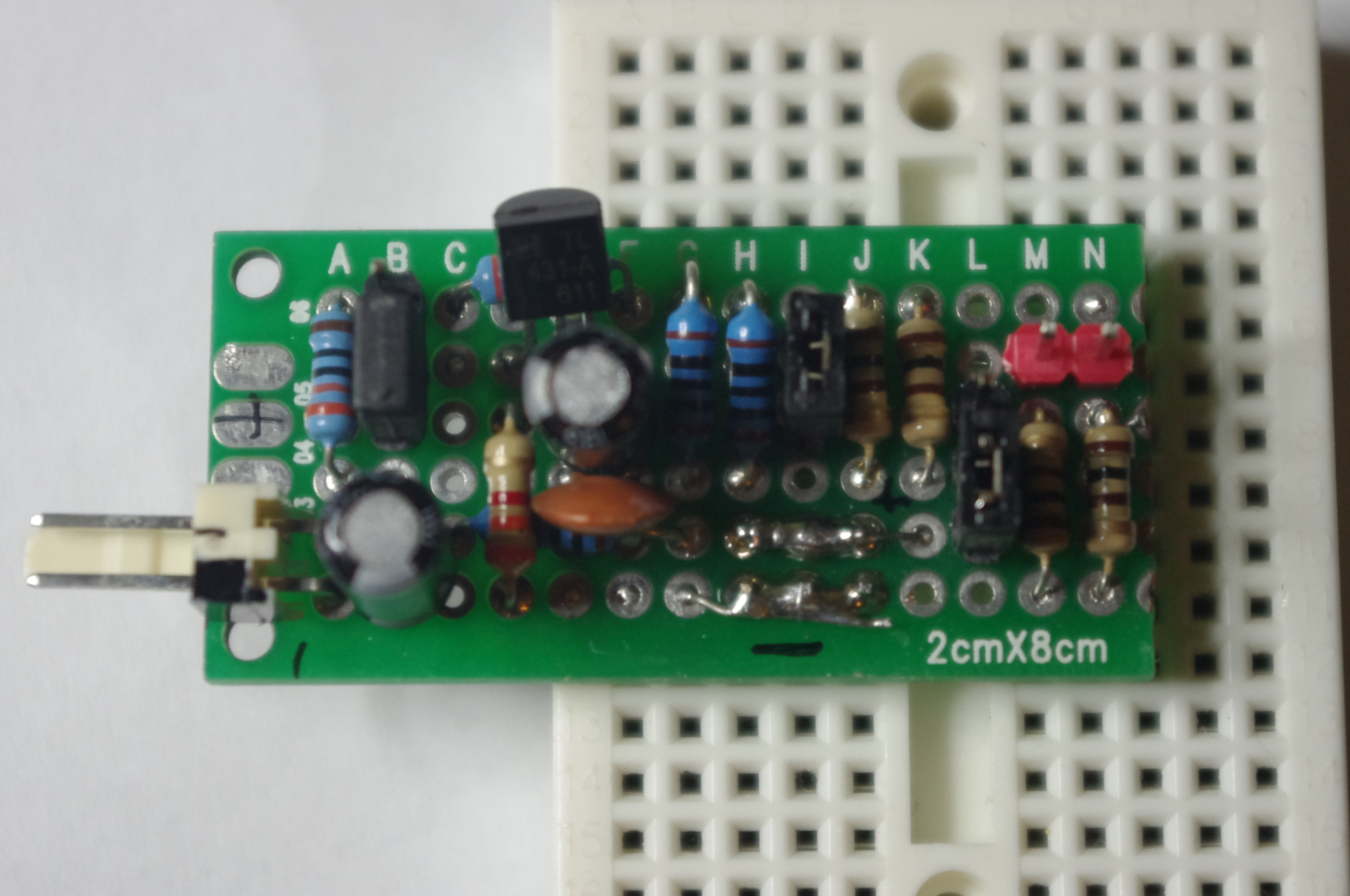
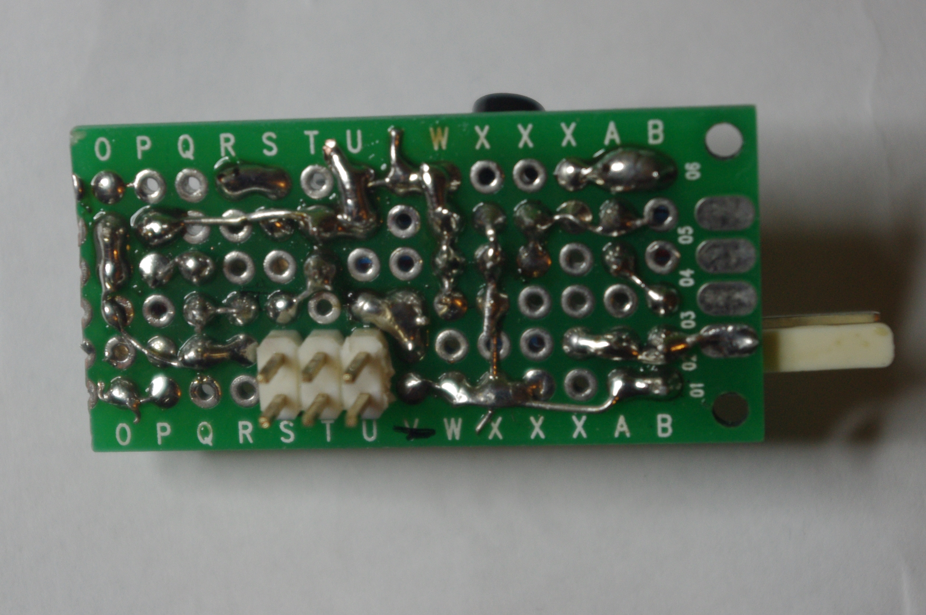
    I built a configurable cr2032 replacement for development. It has 2 voltage modes: 3.0V and 2.75V, and 2 internal resistance modes: 20Ω and 40Ω. There's a current measuring jumper, and a connector for measuring the voltage across the "internal resistance".
    The schematic can be found here.

  • A prototyping board

    piotrb5e301/02/2018 at 22:43 0 comments

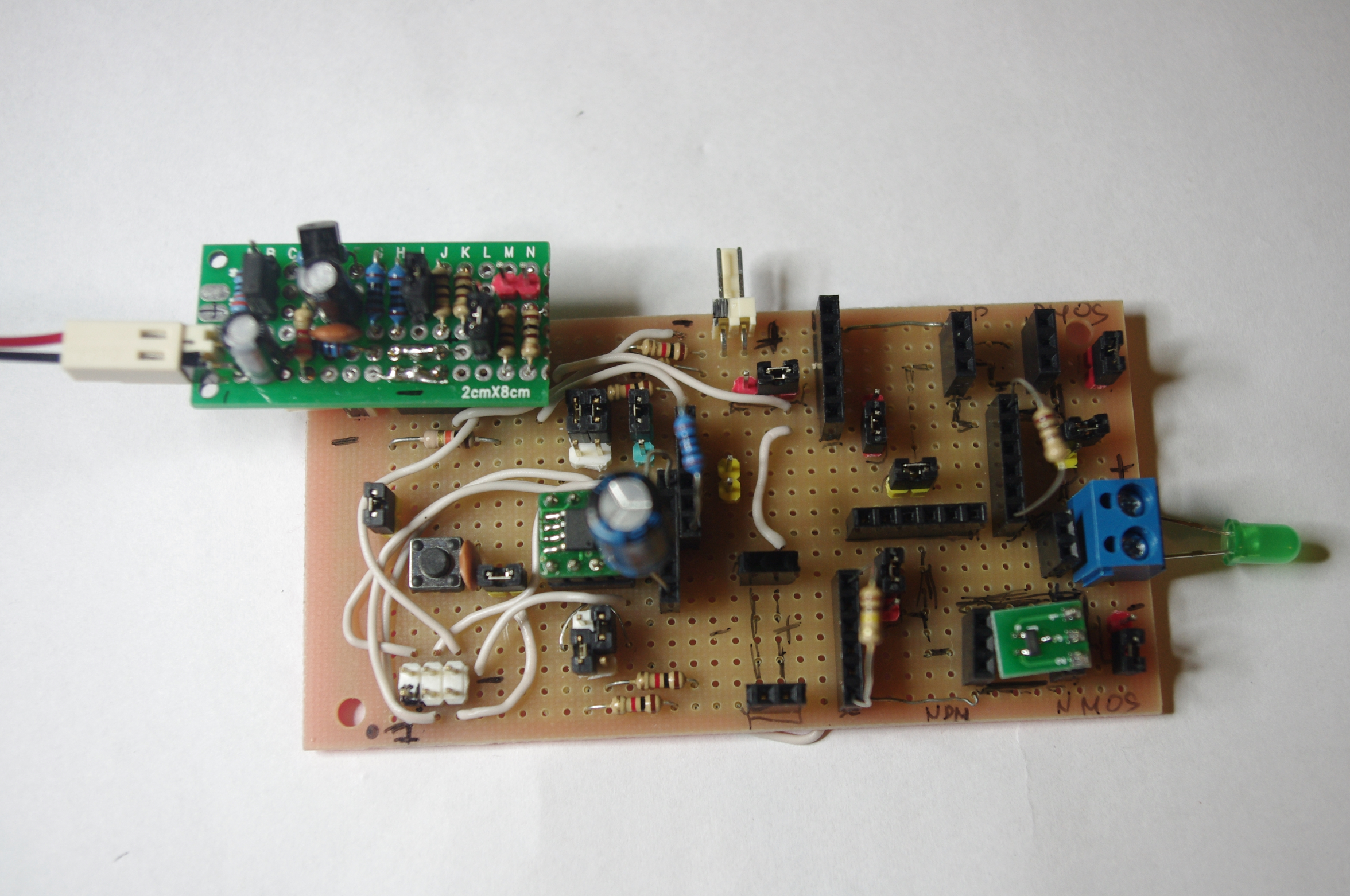
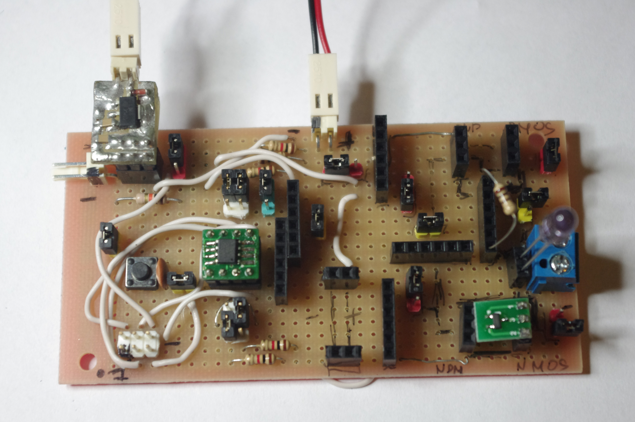
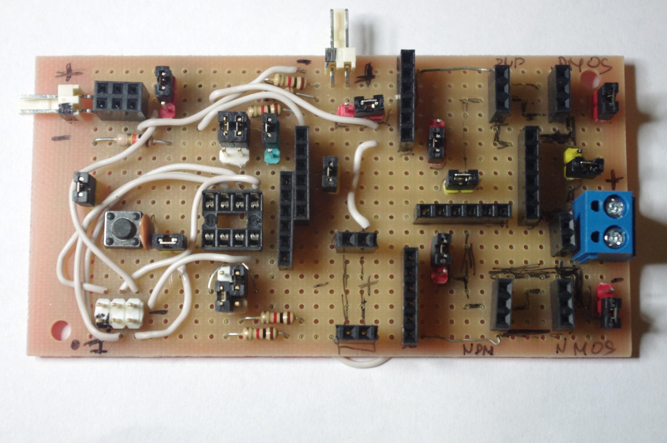
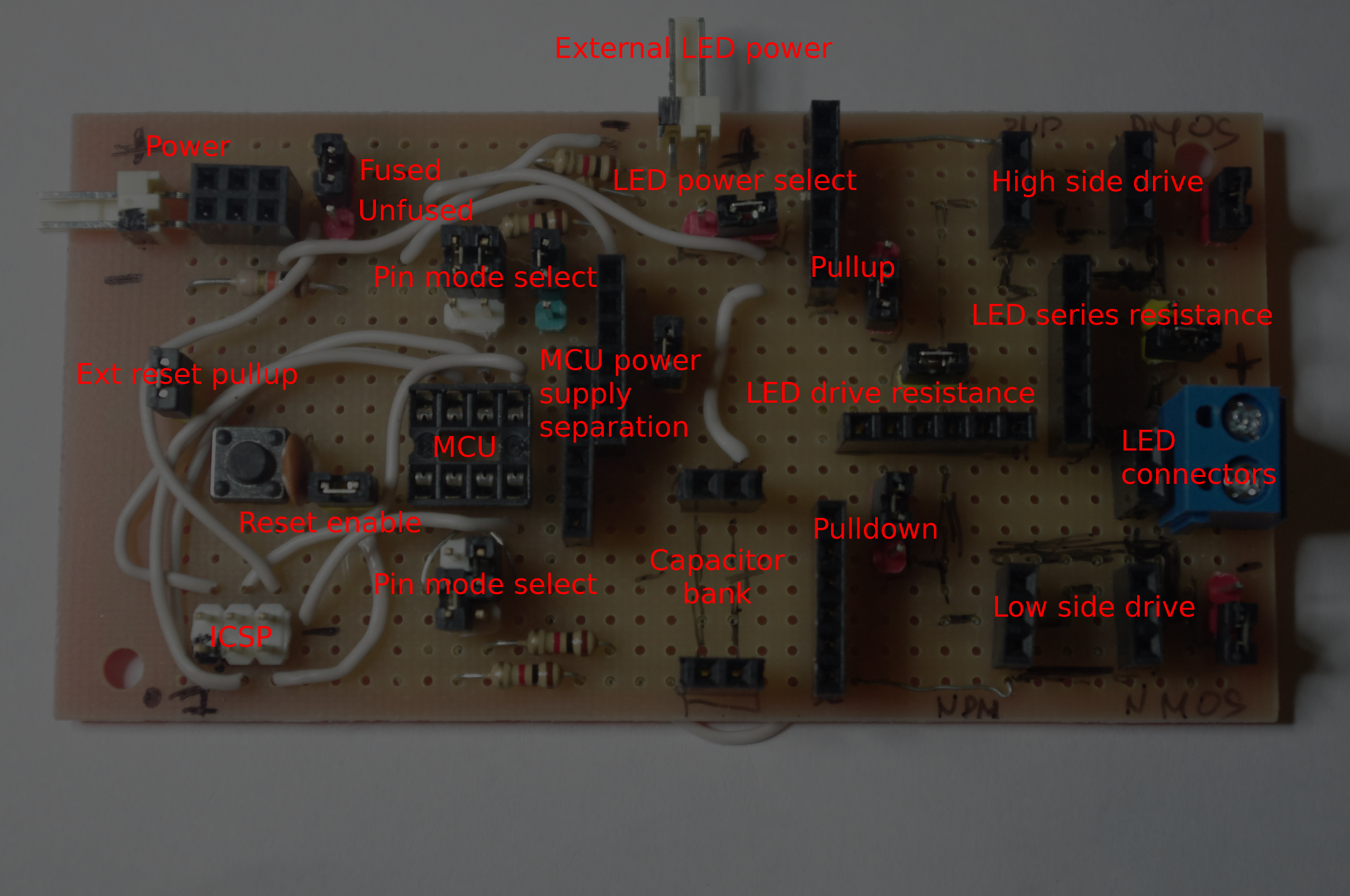
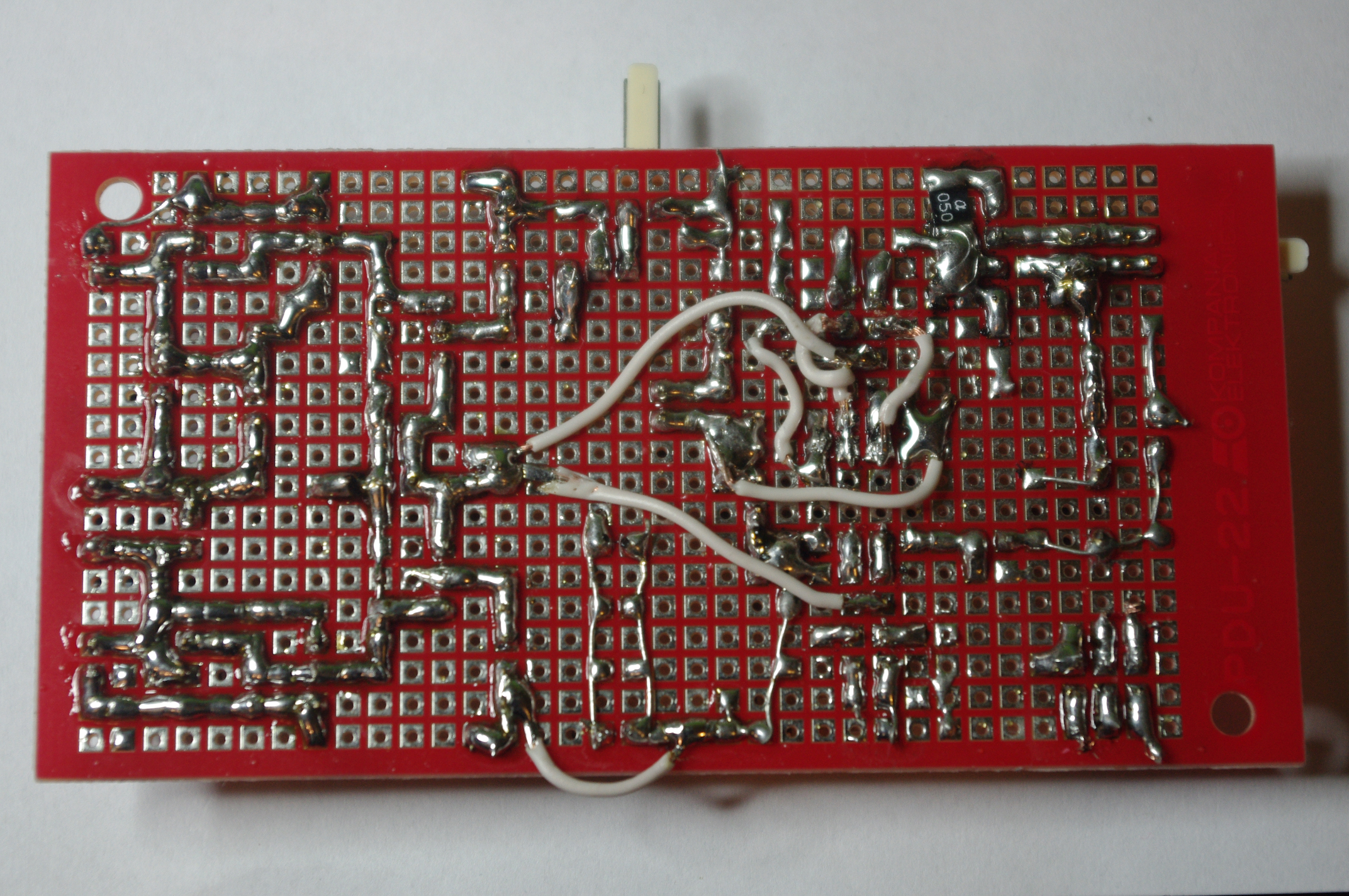
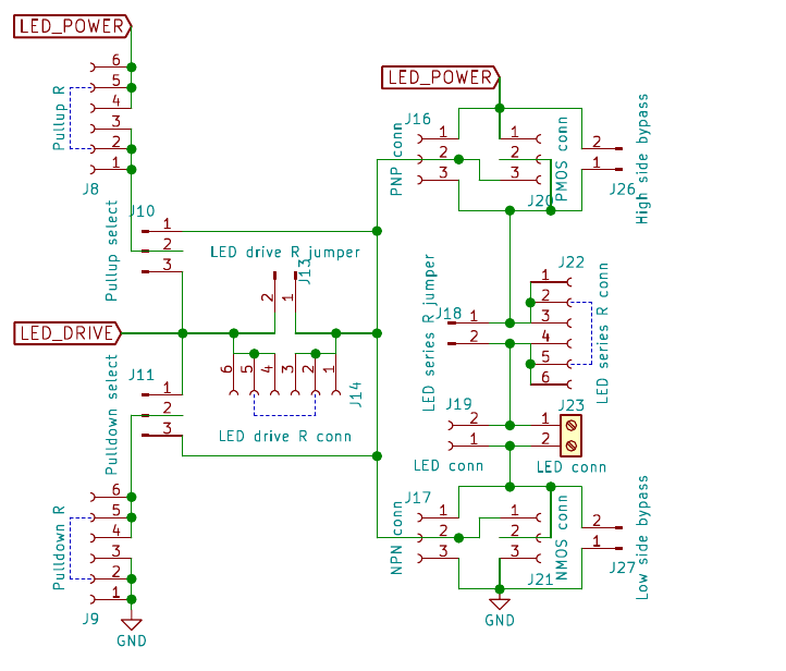
    I built a prototyping board for this project. There were a few changes from the circuit posted in the last log entry. Here's the updated circuit.

    I tried to make it as generic as possible, so it can be used in other, future projects. 

  • How do I drive LEDs again?

    piotrb5e301/01/2018 at 19:10 0 comments

    I designed a circuit to test different LED driving techniques, and measure their efficiency. Yes, this schematic has over 30 connectors/jumpers. Yay configurability!

    The full schematic can be found here.

  • Capacitor leakage and choice of a switching device

    piotrb5e312/31/2017 at 00:15 0 comments

    One possible place of energy loss will be the capacitor array. Because of the high internal resistance of the cr2032 (tens of Ω) it's impossible to drive the LED at 500mA directly from the battery. At least a few hundred μF of capacitance will be needed to deliver the high current pulse. Electrolytics are no good because of their high leakage current (measured around 3μA with a 100μF low ESR one). MLCCs are the only option. 

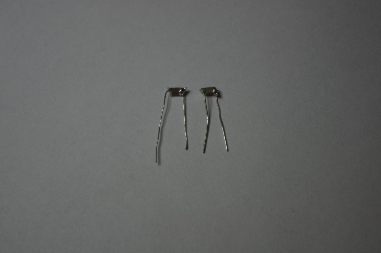
    One of the stores I frequent has just what I need: generic 10μF 10V 1206 X7R capacitors. But what is their leakage current? I had a few of those laying around, so I quickly soldered "legs" to them and assembled a simple measuring circuit.

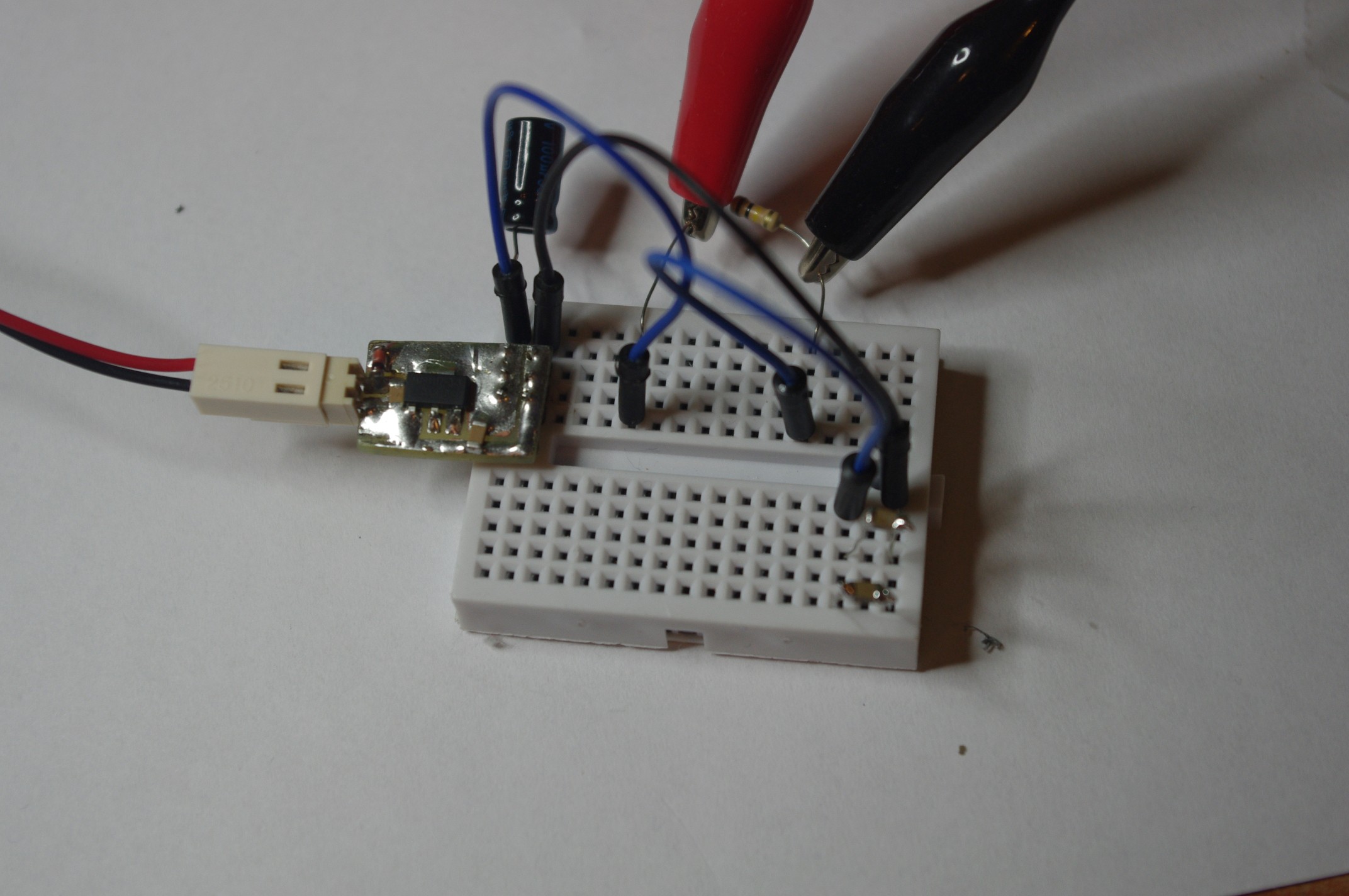
    On the left is a 3.3V regulated supply with an additional large smoothing capacitor (100μF). Then there's a 100kΩ resistor connected from the positive rail to one side of the 2 paralleled caps (lower right). The other end of the caps is connected to ground. A multimeter in voltage mode is connected across the resistor. Initially the resistor is shorted with a juper wire to let the caps fully charge. 

    The measurement came up 0.0 - 0.1 mV. Clearly we're dealing with a really low current here. I swapped the resistor for a 1MΩ one and measured again. This time it measured 4mV and quickly dropped to 2-1mV. After a minute it reads < 1mV. 1mV over 1MΩ is 1nA of leakage current, co we should be able to safely stack up to a 100 of those caps without worrying about battery life.

    Choice of a switching component

    If I'm reading it correctly, this datasheet implies that a base current in the range of tens of mA will be required to drive a 500mA load in saturation mode. Maybe we can do better? I searched the online catalog of the previously mentioned store for a logic level, low RDS(ON) N-MOSFET. I managed to find the IRLML2502. It has RDS(ON) of around 0.05Ω at 2.5V VGS. Seems suitable. I'll get a few and test them against some generic BJTs.

  • Guesstimating LED drive current

    piotrb5e312/30/2017 at 15:58 0 comments

    Let's see how much current can we put through the LED and still make the 1 year battery life goal.

    From the last log we have around 31ms of MCU activity time and 1.5ms of LED-on time. We also have around 180mAh of battery capacity left for transmitting the data.

    From the datasheet we get at most 2mA supply current in active mode using the internal 4.8MHz RC oscillator (divided by 4, all peripherals disabled). We'll try to calculate the maximum number of transmissions from a single battery depending on the LED drive current.

    The formula is:

    Where Ntr is the number of transmissions, Qbat is the battery capacity, Qtr is the capacity used by a single transmission, Iμ and tμ are MCU current and time and ID and tD are LED current and time. We divide the calculated value by 365*24 = 8760 hours in a year to get the maximum number of transmissions in an hour.

    And the calculated values:

    LED currentTransmissions countMax transmissions per hour
    10mA8`415`584960
    100mA3`056`603348
    250mA1`482`837169
    500mA798`02991
    1A414`85247

    We can safely aim for 500mA and 1 transmission per minute. Even with extra losses in the system we'll meet the 1 year battery life goal.

  • Choosing the transmission protocol

    piotrb5e312/30/2017 at 14:37 0 comments

    As I've calculated in the previous log, around 70% of the total power consumption of this project comes from just the driving of the LED. The choice of protocol will have an enormous impact on battery life. My first choice was to use the NEC protocol. Let's see if we can do better.

    Let's look at protocols supported be the Arduino-IRemote library. We'll be using a 33% duty cycle (9μs LED on time).

    NamePayload size
    (bits)
    Max transmission timeIR on time

    (per transmission)

    NEC3286ms8.937ms
    Denon1430.45ms1.44ms
    Panasonic4890ms9.108ms
    RC51225ms4.032ms
    RC61924ms4.032ms
    Sharp1331ms1.728ms
    Whynter32102ms9.507ms


    Let's start with the Denon protocol. Out of the available 14 bits 2 will be used for a checksum. This leaves us with only 12 bits for the password. 4000 combinations is not much, but for this project it should be enough.

  • Rapid prototyping and back-of-the-envelope calculations

    piotrb5e312/30/2017 at 01:22 0 comments

    The choice of a microcontroller

    I searched my drawers for unused MCUs and came up with the following:

    DeviceCurrent consumption
    (in power-saving mode)
    Minimum voltagePackage
    ATmega328P1μA1.8VDIP28
    ATtiny13A4μA1.8VSOIC8
    AT89C20511mA(1)2.7VDIP20
    STM32F070F6P62μA2.4VTSSOP20
    STM32F051K8T60.8μA2VLQFP32
    STM32F103C82.6μA2VLQFP48

    (1) - it has a power-down mode, but the only way to exit it is a hardware reset

    We can discard ATmega328P and AT89C2051 because of large packages. Then STM32F051K8T6 and STM32F103C8 because of hard to solder packages. Looking at a generic cr2032 datasheet we see that the 1.8V minimum supply voltage of ATtiny13A isn't much of an advantage. But the STM32F070F6P6 is a much more complex device. Let's check if halving power consumption is worth it.

    Going back to the datasheet we read that a typical cr2032 has the capacity of around 200mAh. At 2μA it makes for 200mAh/0.002mA = 100000h ≈ 4166 days ≈ 11 years. At 4μA it's ≈ 5.5 years. Scaling it back to our 1 year battery life target we get 9% and 18% of power consumption going to the powered-down MCU respectively. A 9% total efficiency increase is not insignificant.

    Nevertheless I decided to go with the ATtiny13A, as it's a simpler design, and I'm already familiar with it.

    Let there be (invisible) light!

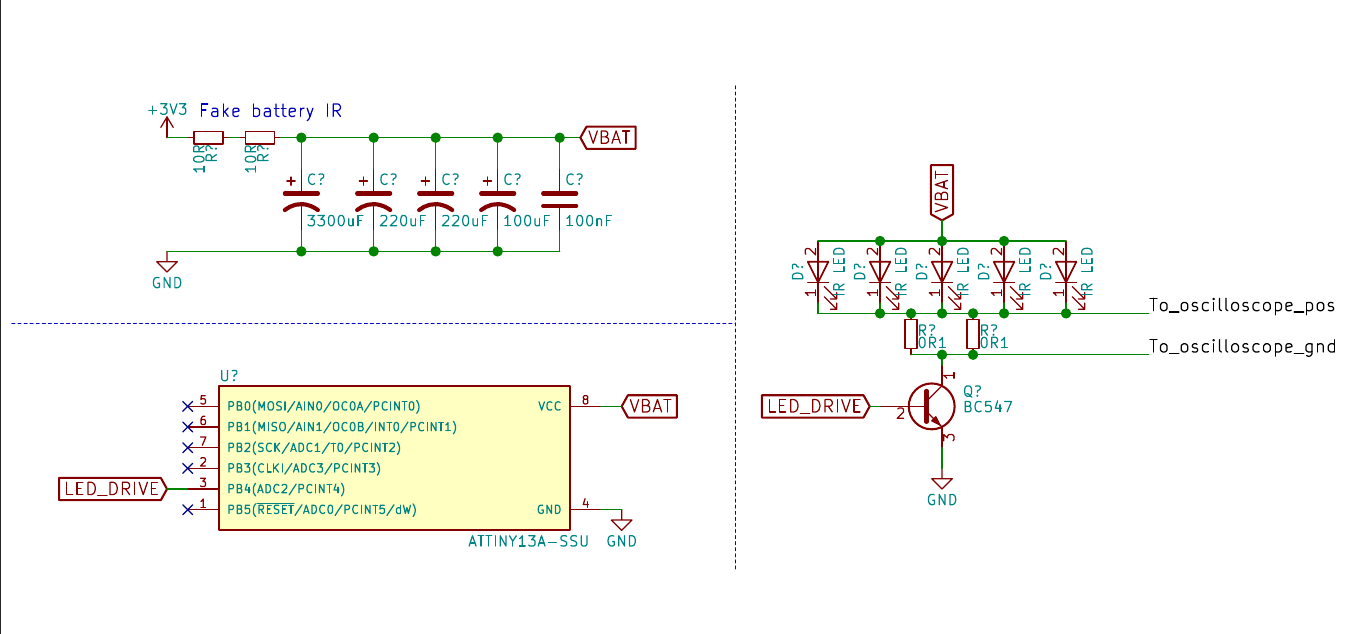
    I quickly wrote a short 38kHz bit banger for the ATtiny13A using the NEC transmission protocol (see the source code), and assembled a simple circuit (schematic PDF).

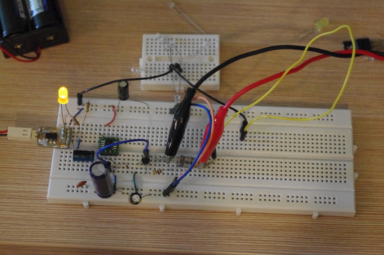
    This is the final iteration. At first I tried driving the IR LED directly from a microcontroller pin, but the range was poor due to a 40mA current limit. A MOSFET would be ideal, but none of those I stock has VGS (th) < 3V.

    I used 2 10Ω resistors in series with a 3.3V regulated power supply to mimick the internal resistance of a cr2032 cell. Multiple large electrolytic capacitors are used to provide a low ESR power rail for high current LED pulses.

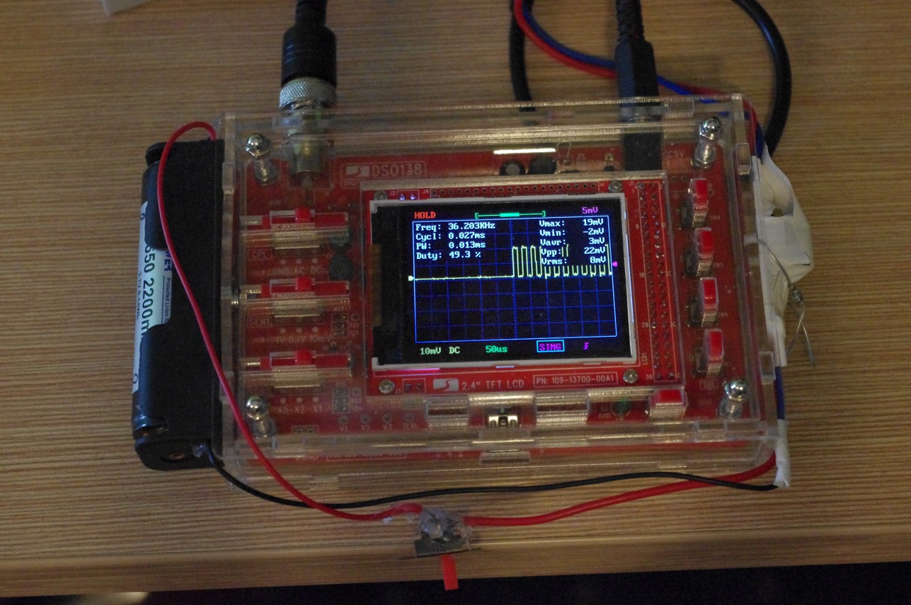
    I measured the peak current with an oscilloscope connected across two paralell 0.1Ω resistors. It peaked at 0.02V over 0.05Ω which gives us 0.02/0.05 = 0.4A = 400mA.

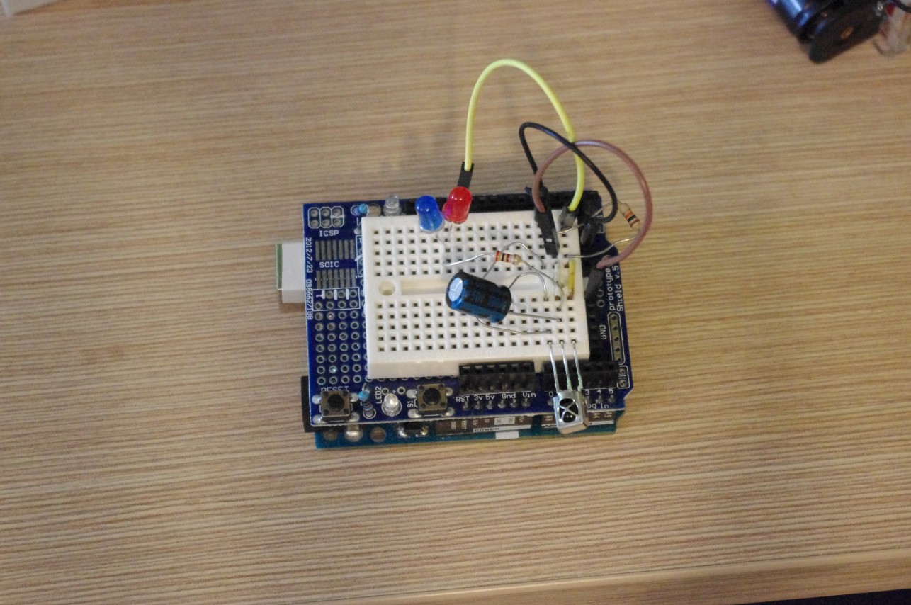
    I built a simple receiver and was able to read the transmitted data clearly across the hallway in my home - around 13m across. Field test will be required to check actual broadcast range. The receiver is a simple circuit with 2 status LEDs - the blue one blinks when the correct sequence was received, and the red one when an incorrect sequence was received.

    The envelope

    Let's dial down the current and consider a 100mA peak drive. A 32-bit transmission with the NEC protocol consists of a 342-pulse header, 32 bit markers of 21 pulses each, and a 21-pulse ending sequence. Each pulse is 13μs long. This gives us 342 + 32*21 + 21 = 1035 pulses per transmission, for a total of 13.455ms of high current draw. Additionally, the microcontroller will be active for at least 70ms at a current draw of around 2mA. This adds up to 13.455ms*100mA + 70ms*2mA ≈ 0.000413mAh.

    After substracting the power needed for the idling MCU we are left with around 160mAh of battery capacity. This will allow us to transmit around 387409 times. In a year, that makes for 387409/(365*24) = 44 transmissions per hour. It's 30% less than my intended target of once-per-minute, but at least we are in the right ballpark.

    One final note: electrolytic capacitors have a considerably high (tens of μA) leakage current. Because of that they should be avoided in low power applications. We'll have to do with just ceramics.

  • Motivation and goals

    piotrb5e312/30/2017 at 00:16 0 comments

    The "Why?"

    This project starts as an entry for the Coin Cell Challenge, but I hope it will outlive it.
    I enjoy microcontroller projects and geocaching. Let's make something that will be fun not only for me, but also for others!

    The "How?"

    The basic idea is to make a beacon that periodically transmits a number. This number will be used a password for a virtual geocache.

    The device should be small and easy to hide. It should last a year on a single battery. The battery must be replaceable. It will be placed outside, so it must be weather-resistant (rain, snow, ice, direct sunlight, temperatures -20°C to +60°C). Transmission must have a broadcast range of at least 20m  (up to 50m if possible). It should follow a well documented protocol. The number should be hard to guess and contain a checksum.

    Construction of a receiver will be left to the geocacher, but example code and schematic should be included.

    The "What?"

    It looks like we'll be needing a microcontroller and some IR LEDs for this one. The rest is up in the air. Let's get prototyping!

View all 9 project logs

Enjoy this project?

Share

Discussions

Elliot Williams wrote 01/10/2018 at 16:49 point

Thanks for that!  It's equally important to know what won't work on a coin cell. 

  Are you sure? yes | no

Similar Projects

Does this project spark your interest?

Become a member to follow this project and never miss any updates