 Audrey Robinel
-
LED Strips - update
04/15/2015 at 01:19 • 0 commentsI tested the LED strips. I did use it in a large aquarium, and they do work. Unlike the neon tubing, they do not heat, cause no IEM interferences (i had electronic parts along the tubes that didn't funtion properly), and should not require to be changed often. Furthermore, i could remove the neon ballasts, removing quite some weight from the system.
As of now, the LED are powered by an ATX PSU, that i'll end up using to also power TEC units to chill the water.
The plants seems happy with it, and the animals in the tank seem unaffected.
However, the light is kind of bluish, and feels dim to the eye. There may be a difference of perception due to the color change, but i'd like it to be brighter. Without a mean to measure actual light output, i'll just rely on my feelings. So i ordered other LED strips : this one from fastech that provides 9000 Lumens in warm white (i also ordered the cold white version, ideally i would have liked the pure white version, but i'll combine both and see how it works), and this strip, that provides 12 000 lumens of cold white (yes, it's over nine thousaaands!).
All in all, yet more cheap led strips from china (but fasttech is less slow/faster than aliexpress). I'll test it out when it arives, but for now i'll just add more led strips to compensate...
In this case, the strips are placed on L-shaped aluminium bars, used to provide both support and cooling. In practice, those LED produced little to no heat, so i could have stuck it on plastic for same results.
So all in all, i'm happy with the principle, but i want to improve either with better LED, or more low quality LED.
I measured the power usage of the system, and with the 3 neon tubes, i did use 130W of power, while now i'm using around 50-60W, including the PSU (power measured at the plug so that's including the pumps).
Since it so much thinner and lighter, i'll be able to get rid of my big white wooden conainer box, and replace it witha lighter structure, held in place with transparant wires.
-
Lights demo
02/20/2015 at 04:18 • 0 commentsToday, i did cut an aluminium plate, and put the 3 LED strips onto it (it has duct tape on the back). I had this plate laying around, so i decided to use it, as it can act as an heat sink if needs be. However, from what i saw, it shouldn't be required, since the LED runs pretty cool.
Anyway, i wired all the LED to my Atmega32U4 board, and sent the serial commands i had programmed. I sent "setLights1FadeIn:60" to have it fade from totally off to totally on over 60 seconds.
The following video shows the result :
(the first caption says "light fading in over 60s", in french, the second one mentions the Atmega32U4 sending PWM signals to the TIP120 transistor controlling the 12V input of the LED, and the last one says that the lights are fully on.
I also made another video to demonstrate how quick the LED turns on and off :
I also sent serial commands : setLights1On and setLights1Off.
The light output seems really high, and it is painful to watch it directly.
However, when placed on the top of my aquarium, i felt like there was less light than with the previous system, so i may end up adding more strips. However, i have to check it properly, since the color difference between the two systems may change drastically the useful light ouput : plants don't care about green light, and yellow is not that important. They use red and blue light more. This LED strip is "cold white", approximately 6000K, so it's more bluish than the previous system.
I conduct some tests later. If i were to add more strips, i would prefer to add warmer light, despite warm light being less efficient, but for a more visually appealing result. After all, the point of an aquarium is to look at it :)
-
LED strips
02/18/2015 at 21:35 • 1 commentAs i mentioned in my previous log, i received led strips from china : http://www.aliexpress.com/snapshot/6379239770.html
I also have waterproof ones, but since they are molded into a silicon strip, i have yet to figure how to solder it. I thus started working with those ones. First of all, they are very bright. The strip is said to consume a bit under 9W per metter. For my smallest aquarium, i cut 3 strips of 45cm, so it should draw aproximately 12W. Each strip of 45cm produces more light than a fluocompact bulb. So here, i'll be increasing the light output and cut the power to less than 1/3 of the previous power usage.
Those strips use 12V DC, so for 1m, they use 0.75A, according to the specs. Here, i'll be using roughtly 1A of current. This is good, because i don't have to use thick wires, nor use beefy transistors. The plan here is to control the LED with a TIP120, driven by an µC pin.
I did try it, and it succeeded. I used an Arduino variant, and i could send PWM to the LED. It worked properly, effectively dimming the LED. They are easy to solder and to work with. A slight downside is that it is not a continuous strip : smaller strips have been soldered together to produce a 5m strip. It causes the strip to be slightly non flat on some bits, and it could be harder to cut if you want to cut exactly where is the solder. However, with a cutting tool it works without any problem. And the strips are really cheap (5-7$ including shipping... for 5 meters!).
If i can send PWM to the LEDs, it means that i can fade the light in, rather than brutally turn it on. I thus made fading functions, with the possibility to specify the total fade time. So now, if i send setLights1FadeIn:time through serial, the strips will fade in in "time" seconds. Without the time argument, it will fade for the duration stored on the chip. I obviously made the corresponding fadeout function. So now, rather than just turn the lights on or off, i will fade them in, in order to reduce the stress for the aquarium inhabitants. I can also now set the max luminosity, so i can adjust how bright the aquarium is lit.
At first, i considered using three relays to turn each light bulb on, to have a "sunrise", but now with the LED i can do it properly.
This first aquarium will thus have 3 strips of 9 packs of LED, each pack containing 3 LED, for a grand total of 81 LED.
According to the spec, i should have 40-55 lumen per LED. If i consider 30Lm per LED, that is still 2430Lm for my aquarium. The previous lights had a max of 800 lumen per bulb, but a significant part were wasted , despite of the reflectors. Here, the light is directed towards the water. Furthermore, i should have little to no light quality degradation over time. As an example, i just noticed that the middle bulb in my aquarium is dead, so less light.
If i consider 40Lm per LED, that's 3240Lm total, and if i consider 55, that's 4455Lm.
I know that the manufacturers often lie about the products, but it is also valid for light bulbs, so this values are a mean of comparison.
For now, i'll underestimate the light output of my system, and dim it if needs be, rather than overestimate, and have to add more LED. Plus i like 81, as it is a power of 3, which is cool, uh?
My second aquarium is 70cm long, and a bit higher. I'll thus use strips of 70cm or less (you have to cut after a pack of 3 LED).
Since it's higher, i'll increase the amount of LED strips (4 to 5). So if i use 65cm strips, that'll consume 5.85W (let's say 6W) per strip, and draw aproximately 0.5A per strip. I'll thus need 6*4=24W to 6*5=30 of power, draining 2-2.5A, still good for a TIP120.
I have 0.6 LED per cm, so i should have 39 LED per strip, producing a low estimate of ~1200Lm per strip, and according to spec, 1560-2145 Lm per strip, for a total low estimate of 4800-6000Lm, and an "spec" estimate of
6400-8580Lm for 4 strips, and 7800-10725Lm for 5 strips.
Considering those numbers, i may end up using only 3 strips, for 3600Lm low estimate, and 4680-6435Lm for "spec" estimate... Or simply use more and dim it if needs be.
More LED means a better light distribution, so why not, after all?
-
Evolution of lighting
01/24/2015 at 17:45 • 0 commentsYesterday, i received white led strips from china. I thus now have quite a lot of LED, enabling me to rethink the lighting of the aquarium. As of now, i was using fluorescent bulbs for one aquarium, another kind of home appliance for the second one, and traditional neon tubes for the third.
I ordered two kind of led strips :
http://www.aliexpress.com/snapshot/6379239770.html and
http://www.aliexpress.com/snapshot/6379239771.html
Those are 5630 LED, known to be quite efficient, with aproximately 25-50 lumen per LED.
According to the specifications, we have 60 led per meter, and aproximately 9W per meter. Specs claim 40-55 lumen per led, i'll be conservative and consider those to have 30-40. Indeed, it will be easier to stop using some LED if i have too much light than adding more LED in my design.
Both LED strips are meant to be used in 12V, and i have 2 reels of 5m of each (i probably won't use that much, but it was cheap, free shipping, so i got extra that i can use for other things. And i have spare, just in case, so that i don't have to wait 2 months!).
I will be using a FSP180-50LE 180W flex atx PSU to power everything. It is very compact (40*80*150mm), and can provide 3.3V, 5V and 12V, with up to 14 amps there. That should be enough to power my LED, and why not, TEC modules to cool the water! I will use the 5V and 3.3V for the electronics, and thus have a reliable power source, rather than using unregulated wall warts.
Those LED are not addressable, but i can cut the strips up to any length. If i consider my shrimp aquarium, i will cut smaller sections of 50cm. Each section,should thus use 4.5W, with 30 led per section giving 900 to 1200 lumen. As of now, this aquarium has 3 fluorescent bulbs, each providing 700-900 lumen. I will thus probably use 3 to 5 sections of LED, and use a transistor to control each, so that i can modulate the light intensity. I'll see if i can use PWM to dim the LED.
Compared to my previous solution, i'll end up with a slimmer light ramp, use less power 10-15W total for the same light output, not have to worry about changing the bulbs often, no need for mains current there, and gain the ability to easily modulate the light intensity. The light will also be well distributed, and since the LED are directional, all the luminous is oriented towards the water. Those LED don't have the best CRI (Color Restitution Index), with 80%, but neither did my previous solution (even lower than 80%). I can anyway compensate with more light if a color is a bit weak for my plants.
See you next!
-
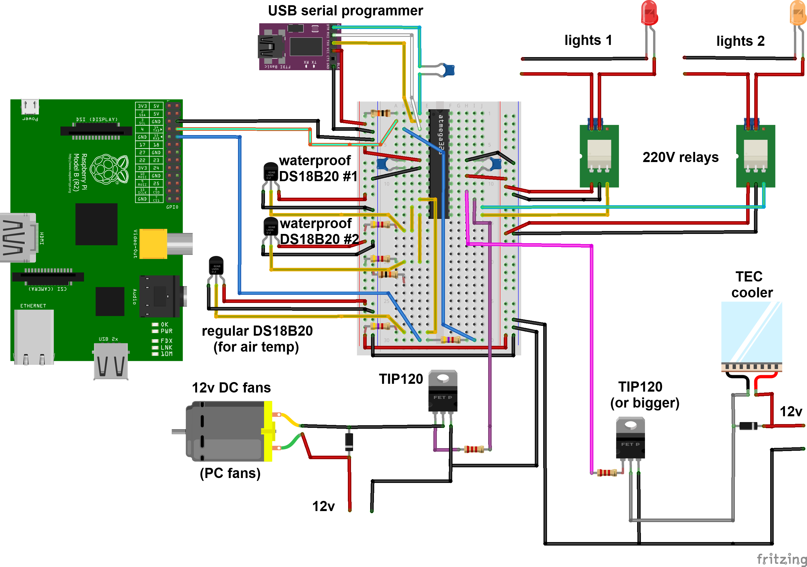
updated schematics with all functionalities
10/16/2014 at 23:45 • 0 commentsHi! Today, i committed a github release containing new files for the project. There is a new fritzing file, along with png, jpg, svg and pdf version of the schematics.
Those file describe the fully functionnal prototype (it has to be tested, updates may come soon). This prototype aims to reproduce and/or enhance the functions of my current system (also based on arduino and raspi but less elaborated).
I also posted an anoted picture :
![]()
So i have two relays for controlling 220V lights (works with 110V of course). As mentioned in a previous post, those are smal relay boards, with protection diode and leds to check if it is working or not. This explains why i just connect those to a gpio without further protection. I have two relays for my two tanks, but more could be easily added, and used to turn the lights on progressively (one tube, then another, etc) or to control more systems. In the end i plan to use LED, so this will change. However, this part of the circuit may be used for whatever mains current device we need to turn on and off.
For DC current devices i use TIP120 transistors. In my case, one for controlling 12v 80mm PC fans (3 in parallel). Those fans are blowing towards the surface, and reduces water temperature of 2 to 4°C.
I included another TIP120 for controlling a TEC that i plan to use for cooling the water further if needed. The TIP120 is rated for 5A continuous use, my TEC is supposed to drain up to 4 amps at 12V, so i'll try it.
At last, i have DS18B20 probes for temperature monitoring. I will include two waterproof ones, in order to monitor both tanks water temperatures, and a regular one to monitor air temperature. This third probe is not really needed, but since i have it, and have spare GPIO, i will include it. For now, the fan is turned on and off depending on water temperature. Later on, it may be PWM controlled, and i may use the air temperature readings to anticipate water temperature rises (if air temp reaches 28°C whereas water is at 24°C as an example, i can monitor how long it takes to warm up the water to a certain temperature, and then decide when to start cooling it to prevent it from warming up then beeing cooled). I could also use it to either use the TEC to cool the water if air temp is too high, or use the fans if it is low enough to save power.
Anyway, it's always nice to have data about the environement of the tanks.
I have a partially done prototype for this circuit, i will complete it and test it. Once i am satisfied with the design i may solder it on stripboard. I also have "perma - protoboards" with a breadboard layout and a raspi ribbon connector, i may try to make an expansion board for the raspi directly.
See you next, with the arduino sketches :)
-
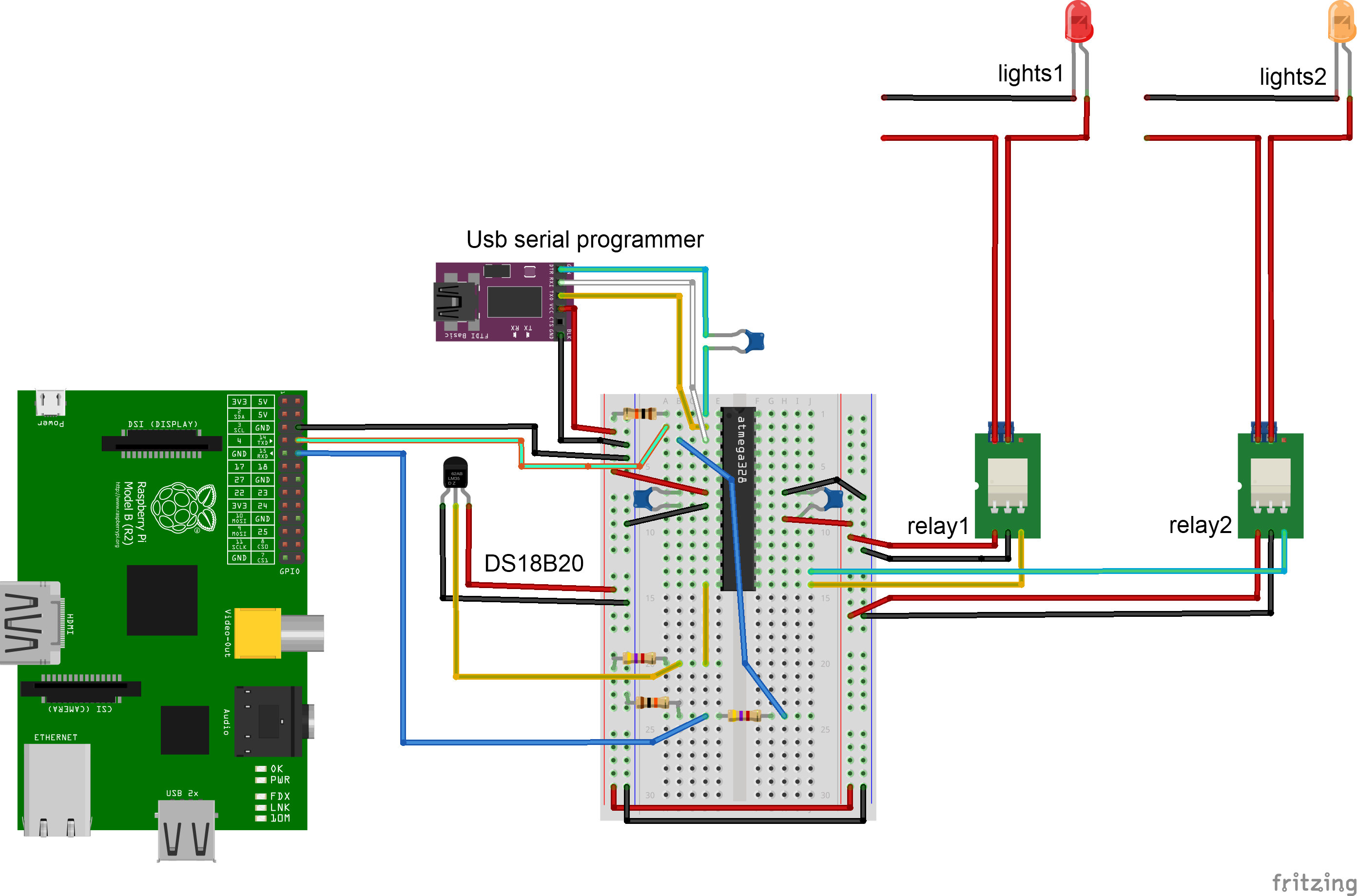
Base circuit schematics
09/18/2014 at 04:07 • 0 commentsIf you only want to monitor water temperature and control two sets of lights, here is a simple circuit i made for testing serial communications:
![]()
I made a breadboard arduino based on an ATMega328p, with the bootlader set for using the internal 8Mhz oscillator. I program it with a serial-usb board, than can stay plugged or not in operation (this way you can read the arduino serial messages both on the Raspberry Pi AND on the Arduino soft, or remove the serial programmer when needed elsewhere).
Be sure to unplug the serial cables before trying to program the arduino, otherwise it will fail, with a message about no sync.
The DS18B20 is connected with a pull up resistor, and the relays are connected to GPIO. If you use bare relays, you have to include a flyback diode and maybe a few more stuff to protect the GPIO from current spikes from the coil. I am using small relay boards, with everything on it. Each relay in my case has a VCC input (5V, red wire), ground (black wire) and a signal wire. There are two screw terminals, for the mains wire. If the signal input is high, the current is allowed to pass trough the relay, otherwise it is not allowed to.
The fritzing file for this circuit can be downloaded in this commit on the github, with the PNG, SVG and PDF version.
In the next version, i will add the transistor used to control the cooling, thus regaining the functionnality of the previous prototype. So stay tuned for the next update, soon!
-
water qualitity sensors
09/17/2014 at 23:31 • 1 commentOn the long term, i'd like to monitor the water quality. The main parameters to monitor are dGH, dKH, pH, dissolved oxygen, CO2 in water, nitrites (NO2-) and nitrates (NO3-). Ideally, we could also measure many parameters (Amonia ->NH3, Amonium ->NH4+ ) that are part of the nitrogen cycle. However, unless the aquarium is not cycled, there should be no ammonia or ammonium. peaks of nitrites may occur when there is a problem in the tank (death of a big animal whose body is left in the tank), but shoudn't normally occur.
![]()
pH should be kept at certain levels according to the population of the tank. Some fish like high pH, neutral or low pH. In my case, i aim for a neutral pH of 7.
Another set of parameters to monitor is water hardness.
Two indicators exist : general hardness (GH) and carbonate hardness (KH). It is often measured in degrees (dGH and dKH) with most tests. Again, here, the target values should be set according to your population. In my case, i aim for 7dKH and a similar value of dGH, since i have caridina cf. cantonensis shrimps, and neocaridina palmata in the same tank (i know the gh and kh values doesn't match with the provided links, but on other websites i found this value. It is really annoying to find the exact value...).
Dissolved oxygen is used to check if there is enough oxygen in the tank. To increase oxygen in the water, you have to make the water surface move. For that, i set the filter outlet in a way that makes movement on the surface, and i have an air pump, making small bubbles, also moving the surface. The hotter the water, the lower the dissolved oxygen in a similar setting. It should not be a problem for my setups anyway.
At last, Carbone dioxyde in water is important for some plants. Some need carbon to be added in water (i have a liquid containing it - easylife carbo -, but gaz form can be dissolved in water too). Too little and some plants don"t grow, too much and animals in the tank die. I tend to put less liquid in my tank than the specification. That way it may not be enough for the plants to grow fast, but it shouldn't kill my tank inhabitants.
Now, on measuring these parameters. The most frequent way of measuring those is chemical tests. Either strips of paper (i have been told by everyone that those are not reliable or precise), or a liquid solution. In this case, you take 5ml of water in the aquarium to be tested, and put a few drops of a solution in the water, and depending on the color, you know the value of the parameter.
This method is cheap, but can't easily be automated. One way to automate it would be to have a peristaltic pump preparing the solution, and either a color measuring sensor, or a camera to assess the color of the solution. However it may prove difficult to fully automate, and you would still have to wash the container after mixing the solution in it, otherwise the next measure will be poluted by the previous one.
I may still work on a semi automated method, where i would make the solution by hand, and have a color sensor or a camera compare the obtained color with the reference colors. This way, it may be possible to extrapolate intermediate values, and the system would store the values rather than have to type it in for later references.
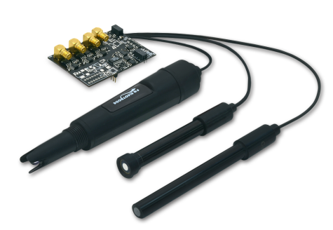
Another solution is to use probes. Probes get immersed in the water, and either return an tension or a value depending on the measured parameter. For automation purposes, it is perfect, since it is what we are used to do with temperature, humidity, etc sensors. However, the downside is that those sensors are expensive (often 100$+ for each sensor) and require a measurement board with amplification to have reliable measurements (often 150$+).
Here is an example of this kind of sensors : http://www.libelium.com/smart-water-sensors-monitor-water-quality-leakages-wastes-in-rivers-lakes-sea/
![]()
Atlas scientific also makes sensors that can be used that way : pH kit at sparkfun, dissolved oxygen at sparkfun.
From what i found on the web, it is possible to make a cheap pH sensor (10-30$). However for the other parameters it seems hard to find cheap solution. I once found a project where a guy was measuring water diffraction to determinate some parameters. It would be a perfect solution, but i didn't find a functional prototype. I think that the author of the project had to callibrate his sensor.
Another problem is that sensors have to be calibrated with a solution, i can't find good informations on how often it has to be done. It is not sure either that those sensors are meant to be immersed continuously in the solution. If not, it means that the system must be calibrated each time, then washed...
All in all, sensors are expensive. Unless i find a new solution, classic sensors are too expensive, except for a few. This part thus a low priority in this project, since other less expensive stuff have to be done before. I am still investigating however. Furthermore, if we consider those parameters, dissolved oxygen doesn't really need to be measured (even if it would be cool to know exact values), as we can ensure that we have high levels. For carbon in water, a precise dosing of the product should ensure correct values. On nitrites, phosphates, ammonia and ammonium, we should not need to measure it. Proper maintenance of the aquarium helps ensuring that everything is good. On nitrates, regular water changes keeps the levels at bay. However i'd like to be able to measure it to find way to extract nitrates from water (with alguea for instance). pH won't change if gH or kH are high enough. If they are low, pH can change easily. At last kH and gH are very low in my case, i have to re-mineralize the tap water. So i will be mixing a solution to obtain a specific value from 0. Unless big changes occur in tap water quality, i should be able to have a recipie for my water (x mg of gh/kh powder per litter). I will probably use drops tests to check the solution when i pepare it. In the absence of anything else, it won't change until i put it in the tank. If i prepare 20-30l of water, i can use it for a few weeks.
Of course, if i find cheap ways to automately measure those parameters, i will try it!
-
Serial communications
09/17/2014 at 05:15 • 0 commentsDue to the planned architecture, i have to be able to communicate in a reliable way between the Raspberry Pi and the Atmega chip. In the previous prototype, i was using simple GPIO commands to exchange information bewteen the two systems.
Indeed, i had a Arduino GPIO controlling the relay (for the lights), and this GPIO was also connected to an LED. I connected a wire after the resistor so that i had lower voltage, lower than 3.3V. This wire goes to the PI, as an input. The pi can thus read the lights status. In order to send commands, another GPIO of the pi is connected to an input of the Arduino. I thus write low - high - low to this GPIO, and the arduino must detect the high folowed by a low to accept the signal. This is also connected to a pushbutton, so in case of failure of the pi, i can manually turn on the lights. When this sequence is sent to the arduino, it inverts the light"s state : from off to on or on to off.
A python script runs on the pi to check the lights status, and turns it on and off when approriate (user defined).
Whereas this works, it is limited. I want to be able to send varied commands to the atmega without connecting tons of GPIO, but also to retrieve data. Indeed, the temperature is also handled by the atmega, and i want to log it on the pi.
I tried both I2C and serial, and found serial to be easier, and more powerfull for what i want to do. I manage to send integer values with I2C, and it is probably possible to send real and text, but it was to much of a hassle. On the other hand, with serial communications, it is really simple : two wires have to be plugged (with a voltage divider on one, or a level shifter), and you send data with Serial.print(...).
I uploaded a simple test sketch for the Arduino and the corresponding python scripts for the pi to the project"s githgub. The Arduino sits there, and awaits a command. When a valid keyword is read, the corresponding command is executed. For now, it can respond to "lightstatus", telling weather the lights are on or off, it can turn lights on and off, and also respond to "waterTemperature" by providing the waterproof DS18B20 sensor reading.
For now those few commands will enable me to provide the same functionality that my previous prototype had, plus a few others easily.
I plan to add an air temperature sensor, maybe a second water temp sensor, and a second relay to control a second tank independantly.
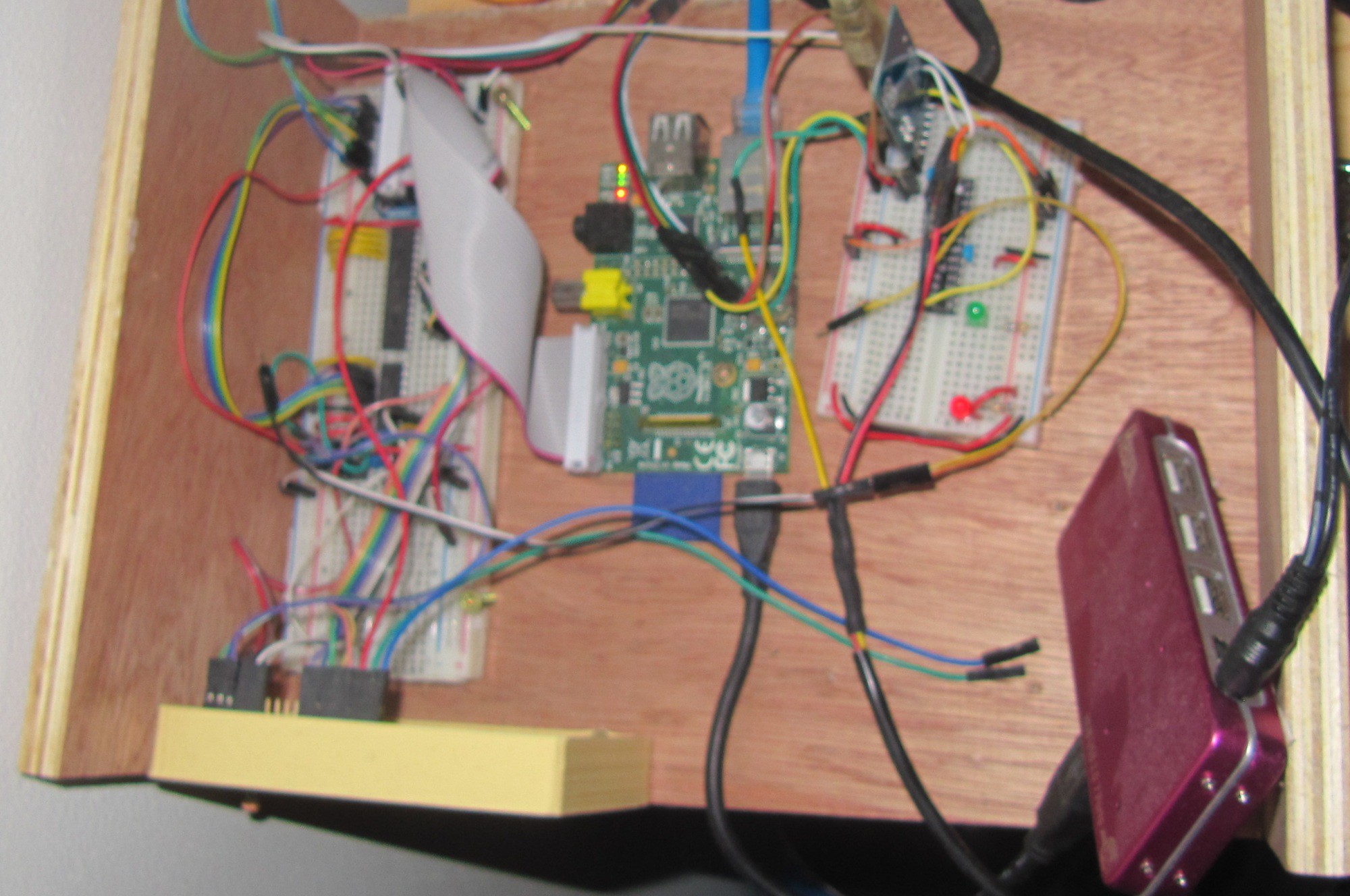
![]()
The new prototype in developpement.
The LCD (4*20, RGB backlight) will print the most important information, and a few buttons will enable the user to control some parameters.
I plan to have the user setting some parameters, that will be saved inside the atmega memory. For now the parameters to be set are the cooling system shutown temperature, and the activation temperature for the same system. As of now, it is set in the Arduino sketch as 24.0 and 24.5.
The current iteration of the system is on a breadboard, i will use a "perma-protoboard" from adafruit later for a more reliable circuit.
See you soon for the next update!
-
General architecture
09/06/2014 at 01:29 • 0 commentsI chose for this project to use a Raspberry Pi for the connected part, storing data, etc. Hovever, i also use a microcontroller (Atmega328p, because i have some, but a Attiny will also do!). I could have used the RaspberryPi GPIO to control the lights and other stuff, and indeed, i did.
For my grand mother tank, that is what i did. The problem is that aquariums are lit by neon tubes (most often, in this case it was), that generates quite a lot of EMI. The problem was that the pi was able to start the neon, but would stop reacting to the buttons afterwards. I had to reboot the Pi to make it work again. I tried to shield the pi with an aluminium plate, but it didn't work. I thus made a quick breadboard arduino whith a atmega328p at 8Mhz (no crystal).
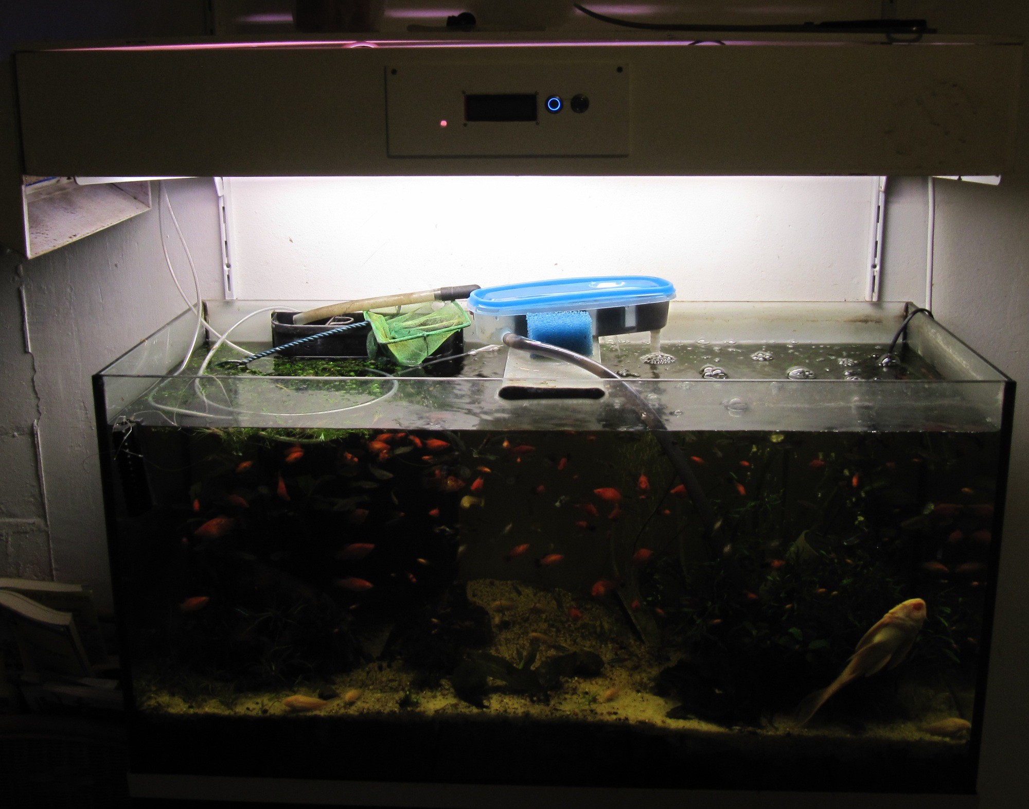
![My granny's tank, with the atmega control for lights]()
On the above picture, the neon box (i made it from plywood) with the button for the lights. The Raspi inside the box doesn't work, whereas the Atmega does. The LCD is off since i removed the Raspi untill i find a solution. For this installation, the fans are always on. The tupperware here is a filter that i made, as the original filter was not efficient enough, and not easy to clean (read more about my filter prototype here).
Even when the breadboard was on top of the neon tube, it kept working. It still does, after a few months. What i learnt from this is that the microcontroller is much more solid and resilient than the pi. It oriented my design choices, and now the architecture is to have a µC controlling the lights and all essential systems. The µC is connected in some way to the Raspberry Pi, that can issue commands to it. That way, even if the pi fails, i can manually control the system through a simple backup interface.
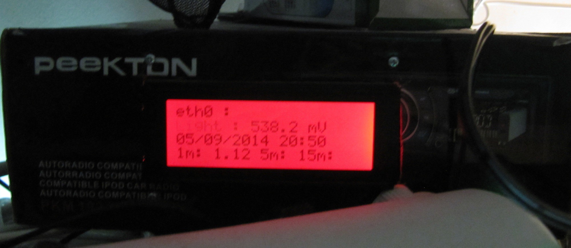
The Raspberry pi is connected to my wifi network, and can thus keep track of time using NTP (i know i could have added a RTC. But i have spare wifi keys, and no RTC clocks...). It then turns on the lights at an user defined time, for an user defined duration (it sends a "on" signal to the atmega, that turns the relay on. After some time, it sends a "off" signal). The Raspberry Pi also has a 4*20 LCD screen for all kind of user feedback (water temp, clock, IP, etc).
![]()
For now, the atmega also handles temperature management , by controlling a 12v transistor to switch 3 80mm PC fans. It senses water temperature using a DS18B20, and turns the fan on when the water temp exceeds 24.5°C, and off when it goes below 24°C. I coded it this way in order to keep the system from constantly turning the fans on and off. Furthermore, a little variation of temperature reproduces natural conditions, and is some times needed for some species to breed.
The air temp in this room is around 26 to 29°C during the day, often lower at night. For now, it is hard-coded, later on it will be set by the user. I will discuss the cooling of an aquarium later in another post, as i am testing pelletier cooling, and i will compare the performance with what i can obtain by simple evaporative cooling (fan blowing towards the water surface).
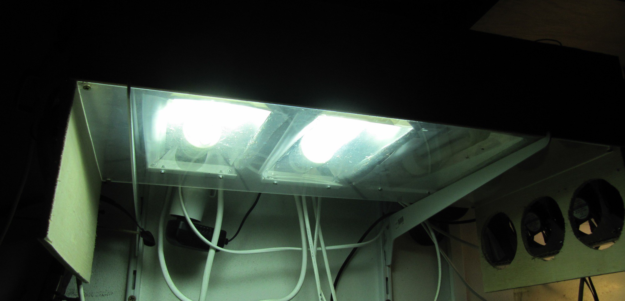
The arduino part, with the fans The lights box, the bulbs beeing protected by a plexyglass plate.
The fans shroud is also visible.![]()
![]()
As of now, other parameters are not yet monitored, i may add a flowmeter to monitor the filter output, and i will be looking forward to montior other physical and chemical parameters of the water.
See you in the next post :)
R'lieh - Aquarium/ closed ecosystem management
An automated and connected aquarium management system

